Mounting and connection
4.5 Wiring the carrier controller
Carrier controller
26
Operating Instructions, 09/2013, A5E03474162-02
Requirement
●
The EMS is powered off.
●
The protective grounding is connected.
●
The EMS carrier is mounted to the EMS
●
All components of the EMS carrier are mounted
●
All cables to be connected are dressed with the corresponding connector.
Procedure
WARNING
Geared motor startup
Insertion of the cable for the geared motor while the carrier controller is powered on may
trigger the unwanted startup of the EMS carrier. This can result in personal injuries or
material damage.
Adhere to the connection sequence. Switch of the carrier controller before you connect the
geared motor.
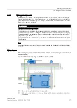
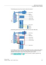
1.
Wire the sensor cables to the –X4 to –X6 interfaces.
The connection is optional.
2.
Connect the braking resistor cable to interface –X3.
The connection is optional and applies when you use a braking resistor.
3.
Connect the L1, L2, L3 and PE cables, as well as the RAIL cable to interface –X2.
4.
Connect the cable of the geared motor to interface –X1.
4.5.6
Securing the cables
Requirement
●
All cables belonging to the carrier controller are connected.
Procedure
1.
Lock the connectors on the carrier controller by means of the provided bracket.
2.
Secure the connected cables by means of cable ties.
Take into account that the rotary frames of the carrier mounts are movable.

