9 – 4
3ZW1012-0WL11-0AB1
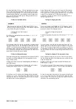
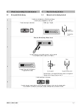
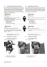
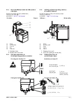
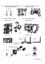
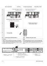
Rücksetzfeder und Bolzen einbauen
1
Rücksetzfeder einsetzen
2
Bolzen mit Sicherungsscheibe einsetzen
3
Bolzen mit zweiter Sicherungsscheibe sichern
Auslösemagnet F5 einbauen
1
Auslösemagnet einsetzen
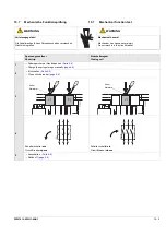
Anschließend
- Überstromauslöser einbauen
- Bedienpult anbauen
→
9.3.2
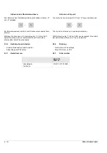
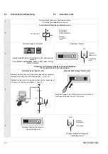
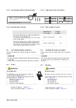
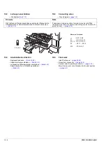
Schilder aktualisieren
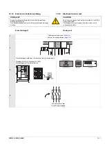
VORSICHT
CAUTION
Während der Installation nicht die Adern des Auslösema-
gneten einklemmen.
Do not pinch the wires of the tripping coil during
installation
Hinweis
Note
Nach dem Einbau zusätzlicher Komponenten sind folgende
Angaben mit einem weißen Permanentstift bzw. mit Aufklebern
aus dem beiliegenden Etikettenbogen zu aktualisieren! Davor
ist es ggf. notwendig die zu korrigierenden Zeichen mit einem
schwarzen Permanentstift zu füllen.
After installing additional components, add the following data
using a white and indelible ink pen or the appropiate label from
the set of labels supplied! If necessary the signs which need to
be corrected have to be filled with a black permanent pen
before.
1
1
0794
click
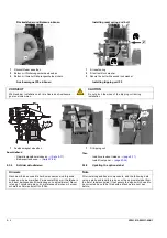
Installing reset spring and bolt
1
Fit reset spring
2
Fit bolt with lock washer
3
Secure the bolt with second lock washer
Installing tripping coil F5
1
Fit tripping coil
Then
- Install overcurrent release
→
- Install front panel
9.3.2
Updating the options label
2
3
2
Содержание 3ZW1012-0WL11-0AB1
Страница 15: ...3ZW1012 0WL11 0AB1 0 XV ...
Страница 87: ...3ZW1012 0WL11 0AB1 8 15 S Auslösung I Auslösung S tripping I tripping ...
Страница 88: ...8 16 3ZW1012 0WL11 0AB1 Erdschlussauslösung Ground fault tripping ...
Страница 251: ...3ZW1012 0WL11 0AB1 14 15 Arranging lock assembly Installing Schlossbaugruppe vormontieren Einbau 0767 1 2 3 4 6 5 ...
Страница 359: ...3ZW1012 0WL11 0AB1 27 5 ...
Страница 360: ...27 6 3ZW1012 0WL11 0AB1 ...
Страница 366: ......
Страница 367: ......

