3ZW1012-0WL11-0AB1
8 – 119
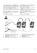
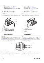
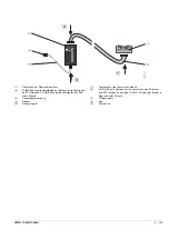
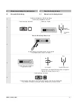
N-Wandler anschließen
Schalter auf die rechte Seite legen
1
Kabelkanalabdeckung abnehmen
2
Überstromauslöser in geeigneter Weise ablegen und freien
Stecker des neuen Kabelbaums in den Kabelkanal einführen
3
Stecker des Kabelbaums mit Stecker des N-Wandlers ver-
binden
4
Verbundene Stecker im Kabelkanal platzieren und Kabel-
kanalabdeckung aufsetzen
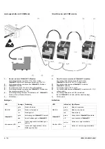
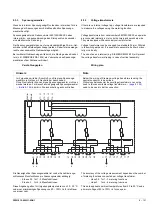
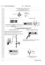
Anschlüsse am Überstromauslösser stecken
Überstromauslöser fixieren und Schalter auf die Füße stellen.
1
Überstromauslöser vor dem Schalter ablegen
2
Stecker an X20 und X21 stecken
3
Kabel mit Kabelbinder fixieren
Anschließend: (bitte wenden)
1
3
4
2
1
3
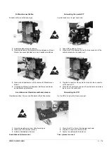
Connecting the neutral CT
Lay the breaker on its right hand side.
1
Take off the cable duct cover
2
Place the ETU suitably and push the free connector of the
cable harness into the cable duct
3
Plug the connector of the cable harness into the connector
of the neutral CT
4
Place the connectors so-joined in the cable duct and replace
the cover on the cable duct
Connecting the ETU
Fix the ETU and place the breaker upright.
1
Place the ETU in front of the breaker as shown
2
Plug the connectors to X20 and X21
3
Fasten the cables with the binders
Then: (please turn over)
2
Содержание 3ZW1012-0WL11-0AB1
Страница 15: ...3ZW1012 0WL11 0AB1 0 XV ...
Страница 87: ...3ZW1012 0WL11 0AB1 8 15 S Auslösung I Auslösung S tripping I tripping ...
Страница 88: ...8 16 3ZW1012 0WL11 0AB1 Erdschlussauslösung Ground fault tripping ...
Страница 251: ...3ZW1012 0WL11 0AB1 14 15 Arranging lock assembly Installing Schlossbaugruppe vormontieren Einbau 0767 1 2 3 4 6 5 ...
Страница 359: ...3ZW1012 0WL11 0AB1 27 5 ...
Страница 360: ...27 6 3ZW1012 0WL11 0AB1 ...
Страница 366: ......
Страница 367: ......

