Description of the individual safety relays
3.7 3TK28 safety relays with solid-state enabling circuits
3TK28 safety relays
118
Manual, 07/2016, NEB926157502000/RS-AB/003
3.7.2
3TK2841 safety relay
3.7.2.1
Applications
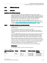
Applications of the 3TK2841 safety relay
You can use the 3TK2841 safety relay in EMERGENCY STOP devices according to
DIN EN / IEC 60947-5-5 and in safety circuits according to DIN EN / IEC 60204-1, e.g. with
movable guards and protective doors or with contactless protective equipment according to
DIN EN / IEC 61496-1, electrical equipment of furnaces according to VDE 0116 and
automatic gas burner control systems for gas burners according to DIN EN 298. Depending
on the external circuitry, a max. performance level PL
e
/ Cat. 4 per DIN EN ISO 13849-1 or
SIL 3 per DIN EN / IEC 62061 can be achieved with this device.
The device can monitor safety shutdown mats with evaluation according to the cross-circuit
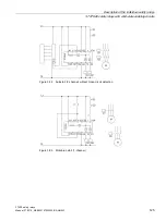
principle (see Figure 3-54 Safety shutdown mat (Page 126))
3.7.2.2
Description of function and connection information
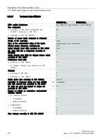
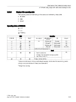
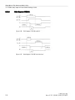
The solid-state 3TK2841 safety relay has two safe solid-state outputs. The operating state
and functioning are indicated by three LEDs. On startup, the device runs a self-test in which
the internal electronics are checked for correct functioning. All internal parts of the circuit are
cyclically monitored for faults during operation.
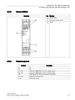
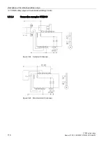
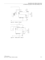
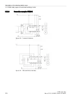
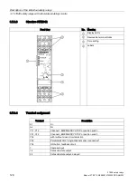
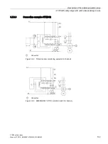
Connect the EMERGENCY STOP button or the position switches or light array to terminals
Y11, Y12, and Y21, Y22. Connect the ON button in series with the NC contacts of the
external actuators to the supply voltage L+ (24 V DC) and to terminal Y34. The cascade
input 1 must either be routed via a safe output or directly to supply voltage L+ (24 V DC).
External actuators or loads can be connected to safe outputs 14, 24. Make sure that the
actuators or loads and the 3TK2841 solid-state safety relay have the same ground potential.
Parallel connection of outputs 14 and 24 to increase the load current is not permissible.
If solid-state sensors are used (light array monitoring, etc.) and in single-channel operation,
Y35 must be connected to L+ (24 V DC). For autostart operation, Y32 must be routed
directly and Y34 via NC contacts of the external actuators to L+ (24 V DC).
Содержание 3TK28
Страница 188: ...Mounting 4 4 Disassembling the device 3TK28 safety relays 188 Manual 07 2016 NEB926157502000 RS AB 003 ...
Страница 204: ...Dimension drawings 6 1 Dimension drawings 3TK28 3TK28 safety relays 204 Manual 07 2016 NEB926157502000 RS AB 003 ...
Страница 206: ...Accessories 3TK28 safety relays 206 Manual 07 2016 NEB926157502000 RS AB 003 ...


