Description of the individual safety relays
3.6 3TK28 safety relays with relay enabling circuits
3TK28 safety relays
Manual, 07/2016, NEB926157502000/RS-AB/003
47
3.6.3
3TK2822 / 3TK2823 safety relays
3.6.3.1
Applications
Applications of the 3TK2822/23 safety relay
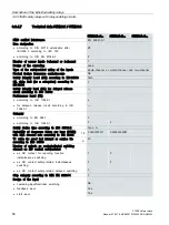
You can use the 3TK2822 safety relay in safety circuits according to DIN EN / IEC 60204-1,
e.g. on movable guards and protective doors.
You can use the 3TK2823 safety relay in EMERGENCY STOP devices according to
DIN EN / IEC 60947-5-5. Depending on the external circuitry, a maximum performance level
PL
e
/Cat. 4 in accordance with DIN EN ISO 13849-1 or SILCL 3 in accordance with
DIN EN/IEC 62061 can be achieved with this device.
3.6.3.2
Description of function
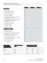
The 3TK2822/23 safety relays have two instantaneous redundant enabling circuits with NO
functions. The enabling circuits are for the safety-related deactivation of actuators.
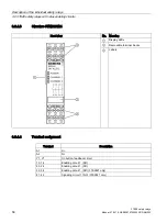
Diagnostics is performed using three LEDs.
The 3TK2822/23 safety relays are suitable for monitoring actuator and sensor circuits
according to DIN EN / IEC 60204-1 in "Autostart" or "Monitored start" mode (depending on
device variant).
When the EMERGENCY STOP buttons are released or position switches operated and the
ON button is pressed, the internal circuit of the safety relay and the external contactors are
monitored to ensure that they are functioning correctly.
If monitoring results in a fault-free state, it is possible to start the device using the ON button
(in "monitored start" mode). This closes the enabling circuits. In "Autostart" mode, starting
and therefore closing the enabling circuits is initiated directly after closure of the sensor
contacts upon detection of the fault-free state.
The number of enabling circuits can be increased by adding one or more 3TK2830
expansion blocks.
With the safety relays, the ON circuit Y33/34 is checked for short-circuit. That means it is
identified as a fault if Y33/34 is closed before the EMERGENCY STOP button is reset.
The devices also monitor the sensor circuits for cross-circuits. This is done based on various
potentials in the sensor circuits.
3.6.3.3
Connection advice
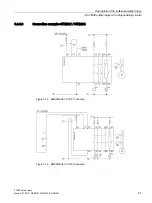
Connect the EMERGENCY STOP button or the limit switch to terminals Y11, Y12, Y21, and
Y22. Connect the ON button in series with the NC contacts of the external contactors
(feedback circuit) to terminals Y33, Y34. (See Chapter Connection examples 3TK2822 /
Содержание 3TK28
Страница 188: ...Mounting 4 4 Disassembling the device 3TK28 safety relays 188 Manual 07 2016 NEB926157502000 RS AB 003 ...
Страница 204: ...Dimension drawings 6 1 Dimension drawings 3TK28 3TK28 safety relays 204 Manual 07 2016 NEB926157502000 RS AB 003 ...
Страница 206: ...Accessories 3TK28 safety relays 206 Manual 07 2016 NEB926157502000 RS AB 003 ...


