


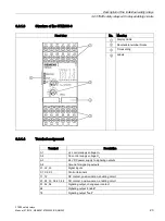


Description of the individual safety relays
3.6 3TK28 safety relays with relay enabling circuits
3TK28 safety relays
22
Manual, 07/2016, NEB926157502000/RS-AB/003
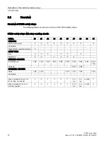
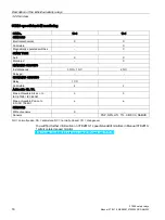
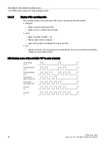
Device properties
●
PL
e
per EN ISO 13849-1; SIL 3 per IEC 61508 / IEC 62061
●
Wire-break detection in the measurement circuit
●
Positive-action safe output contacts: 3 NO contacts, 1 NC contact for 250 V AC
●
2 semiconductor signaling outputs
●
1 changeover signaling output
●
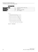
Settable voltage threshold U
an
●
Settable standstill time t
s
●
LED displays for motor standstill, wire break, and operating voltage
●
Suitable for use with frequency converters
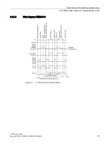
Practical note (operation with frequency converter)
A frequency converter generates an offset during braking (DC component). This can be
detected as a wire break and stored by the standstill monitor. The same operation also
occurs during DC braking.
The enabling circuits are only released when:
●
braking has ended, i.e. the standstill monitor no longer detects a DC component (-> motor
stopped) and control terminals X2 - X3 are jumpered.
●
or a manual reset is performed via these terminals.
If the 3TK2810 is used with a frequency converter, terminals X2 - X3 must be jumpered or a
manual reset must be performed before restart.
Use of control terminals X1 / X2 / X3
●
Feedback circuit X1-X2: Use a floating contact here that provides appropriate isolation for
the level of maximum measurement input voltage (motor voltage).
●
Reset X3-X2: For instance, if you control terminal X3 from a PLC via a coupling relay, use
a floating contact here that provides appropriate isolation for the level of maximum
measurement input voltage (motor voltage).
WARNING
Hazardous voltage!
Can cause electric shock and burns.
The control terminals X1 / X2 / X3 are not electrically isolated from the measurement inputs
L1 / L2 /L3.
For this reason only use floating contacts for the control terminals.
Содержание 3TK28
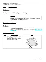
Страница 188: ...Mounting 4 4 Disassembling the device 3TK28 safety relays 188 Manual 07 2016 NEB926157502000 RS AB 003 ...
Страница 204: ...Dimension drawings 6 1 Dimension drawings 3TK28 3TK28 safety relays 204 Manual 07 2016 NEB926157502000 RS AB 003 ...
Страница 206: ...Accessories 3TK28 safety relays 206 Manual 07 2016 NEB926157502000 RS AB 003 ...