


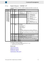


Connector Pin Assignment
Mating con-
nector X16
Pin
I/O
Name
Configurable functions
7
I
IN6
▶
No function
▶
Error reset
▶
External hardware OK
▶
Speed direction
▶
Teach no-load current
▶
Parameter set Bit 3
▶
Internal target value Bit 1
▶
MOP up
▶
MOP down
8
I
IN7
▶
No function
▶
Error reset
▶
External hardware OK
▶
Speed direction
▶
Teach no-load current
▶
Parameter set Bit 4
▶
Internal target value Bit 0
▶
MOP up
▶
MOP down
9
I
TEMP
Motor temperature sensor (towards GND)
10
I
AIN0+
(2)
Reference speed value (reference to ground)
(pin coded)
11
I/O
GND
Ground
12
I/O
GND
Ground
(1)
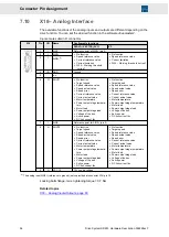
See also X17.
(2)
In order to use this analog input, make the following setting in the software
drivemaster2
: Activate the parameter “Sin-
gle-ended” for “Analog-In 0”.
Specification of terminal connections
▶
Conductor cross-section solid/stranded: 0.14 to 1.5 mm²
▶
Tightening torque: 0.22 to 0.25 Nm
Related topics
X16/17 – Digital Inputs, page 67
Temperature Sensor of the Motor, page 79
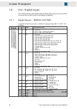
7.9
X17 – Motor Feedback
For all main measuring systems
Available measuring systems: resolver, sine cosine encoder, incremental encoder TTL
(5.3 V), incremental encoder 12 V, Hall encoder (5.3 or 12 V), linear Hall encoder, field
plate sensor, Heidenhain EnDat encoder, Hiperface encoder, encoder
A NAMUR sensor is connected to X15/pin 6.
NOTICE
Voltage (VCC) varies depending on the set measuring system
When the connected measuring system is operated under a wrong voltage, it can be
damaged.
→ Check that you have chosen the right measuring system in the software
before
connecting
.
52
Drive System SD2M - Hardware Description 036228xxF