


7.7.2
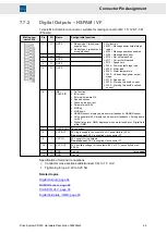
Digital Outputs – HSPAM / VF
12-pole Mini-Combicon connector, suitable for mating connector MC 1,5/ 12-ST-3,81
(Phoenix)
Mating con-
nector X15
Pin
I/O
Name
Configurable functions
1
O
OUT0
▶
Ready type 1 (with power
supply okay)
▶
Ready type 2 (without pow-
er supply okay)
2
O
OUT1
3
O
OUT2
4
O
OUT3
5
O
OUT4
▶
No function
▶
M01 – Message power output stage
ready
▶
M02 – Message operation enabled
▶
M03 – Message drive error
▶
M10 – Ref. value reached
▶
M11 – Current limit reached
▶
M12 – Speed zero
▶
W04 – Power output stage load
▶
W05 – Motor load
▶
W07 – Motor temperature
▶
W09 – Undervoltage power output
stage
▶
W12 – Speed error
▶
W24 – Warning threshold ’current'
▶
W26 – Warning threshold ’overload
current'
6
I
IN8 /
PULSE IN
▶
No function
▶
Error reset
▶
External hardware OK
▶
Speed direction
▶
Teach no-load current
▶
Parameter set Bit 5
▶
MOP up
▶
MOP down
▶
NAMUR sensor; displayed, when motor feedback = NAMUR sensor
▶
Pulse generator 24 V; displayed, when motor feedback = Pulse genera-
tor 24 V
▶
Digital field plate / GMR; displayed, when motor feedback = Digital field
plate / GMR
7
O
PULSE OUT Speed pulses
8
I
VCC EXT
24 V logic supply in the event of an AC power failure (0.5 A)
Do not connect:
24 V is supplied via connector X1.
9
I
VCC IO
24 V supply for the outputs
Do not connect:
24 V is supplied via connector X1.
10
O
VCC OUT
24 V auxiliary voltage for the outputs (24 V ±10 %, uncontrolled, max.
0.25 A)
11
I/O
GND
Ground
(pin coded)
12
I/O
GND
Ground
Specification of terminal connections
▶
Conductor cross-section solid/stranded: 0.14 to 1.5 mm²
▶
Tightening torque: 0.22 to 0.25 Nm
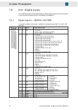
Related topics
Digital Outputs, page 64
NAMUR sensor, page 64
PULSE IN 24 V, page 65
Digital field plate / GMR, page 65
49
Drive System SD2M - Hardware Description 036228xxF
Connector Pin Assignment