


Connector Pin Assignment
7
Connector Pin Assignment
7.1
ID switch (Address Selection Switch)
➮
Set the address for the module by means of the address selection switch.
16 adresses are available: 0, 1, 2, 3, 4, 5, 6, 7, 8, 9, A, B, C, D, E, F. (When the de-
vice is connected via SERVOLINK 4 only 12 addresses are available (0 to B).)
Note
The addresses of several devices in a system must be different from each other to
ensure that they can be identified by the software.
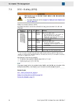
7.2
X1 – 24 V
24 V logic supply as well as status message from external power supply unit
Note
The 24 V logic voltage must be connected (for logic maintenance/cooling).
4-pole Combicon connector, suitable for mating connector MSTB 2,5/ 4-ST-5,08 or
MVSTBW 2,5/ 4-ST (Phoenix)
Mating connector X1
Pin
I/O
Name
Meaning
4
I
24 V
Logic voltage 18 to 28 volts
3
I
0 V
Logic voltage 0 V
2
I
ERR0
Error code 0 of external power supply
unit
(MSTB 2,5/ 4-ST-5,08)
1
I
ERR1
Error code 1 of external power supply
unit
Specification of terminal connections
▶
Conductor cross-section solid/stranded: 1 to 2.5 mm²
▶
Tightening torque: 0.5 to 0.6 Nm
Note
ERR0 and ERR1 must only be connected when an external power supply unit is used.
The signals ERR0 and ERR1 transmit the status of the external power supply unit to the
drive amplifier. These signals are generated by each power supply individually and must
not be connected between two power supply units. This also applies to the power supply
units of compact devices.
Related topics
X1 – 24 V, page 60
Connection Diagram, page 111
44
Drive System SD2M - Hardware Description 036228xxF