


Chapter
3
Operating Instructions
UE4155
14
© SICK AG • Industrial Safety Systems • Germany • All rights reserved
8010178/TF82/2010-03-05
Subject to change without notice
Product description
The following advantages are to be had by using the UE4155 bus node:
cost-savings on purchase: The components to be connected do not have to have their
own PROFIBUS slave.
improved use of PROFIBUS capacity: Only one PROFIBUS slave is necessary for several
components of an application.
integration of
all
the functions of present and future SICK safety components with an
SDL interface without loss of functionality
lower cost of wiring on the PROFIBUS side as several components are connected as a
PROFIBUS user
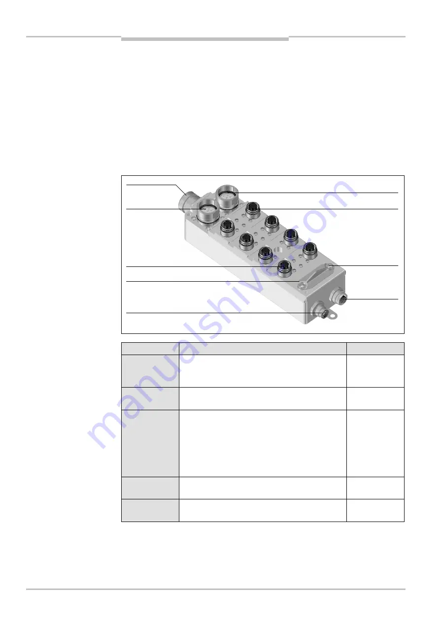
3.2.3
Device construction
Connection
Function
See also
Power supply
Common voltage supply for UE4155 and the safety
components connected to the SDL and field-signal
connections
SDL
connections
To connect safety components to SICK device
communication and/or OSSDs
Field-signal
connections
To connect OSSDs and passive components, e.g.
switches fitted with contacts to voltage-free
contacts
1 field-signal connection = 2 channels
(2 safety inputs and 2 outputs)
Connections can be shared by a two-way splitter
Configuration
connection
To directly connect a PC to the SICK CDS in order to
configure the system
PROFIBUS
connection
Input and output according to PROFIBUS
specification
Please refer to chapter 10 “Technical specifications” on page 55 for the data sheet.
A dimensional drawing is included on page 61.
Fig. 2: Construction of the
UE4155 bus node
Tab. 2: Connections of the
UE4155 bus node
SDL
connection 2
Field-signal connection 1
Switch for
PROFIBUS
addresses
(covered)
Configuration connection
(covered)
PROFIBUS input
PROFIBUS
output
Field-signal connection 8
SDL connection 1
Power supply