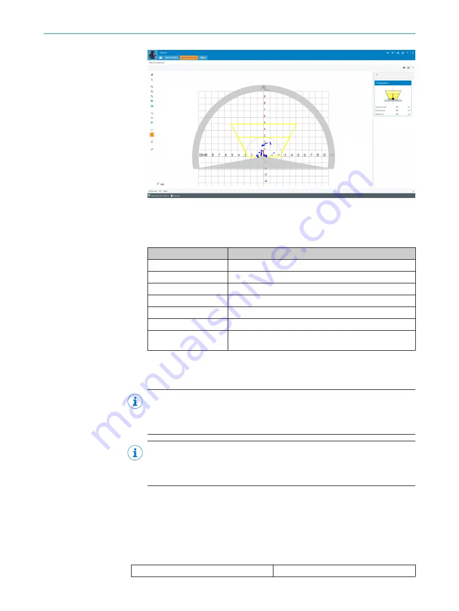
The
Edit field points
tool (mouse pointer in the list of tools to the left of the scan
view) can be used to customize the field geometry with the assistance of the
mouse pointer. Alternatively, the field vertices can also be customized by entering
the coordinate values in the
Field coordinates
mask.
Table 3: Options for editing the field geometry with the mouse pointer
Function
Procedure
Scale field
Drag square red handle.
Rotate field
Drag round black handle.
Customize field shape
Drag square green handle.
Add field vertices
Double-click in required position.
Delete field vertices
Click to select square green handle and press the
[del]
key.
Delete field
Press the
[del]
key without first selecting a green handle.
Insert new field
Select the
Insert field points
tool, click to set field vertices, and
double-click last field vertex to close the field.
•
Complete
: Scan display (left-hand side) and buttons to finalize the device parame‐
terization, report display and system diagnostics (right-hand side of the
Configura‐
tion
tab), along with text boxes to describe the configuration (right-hand side of the
Description
tab).
NOTE
The device requires a detection field to operate and will go into service mode if
there is no detection field. Factory reset the device to restore the default detection
field.
NOTE
Changes to parameters that are made in SOPAS ET are not saved automatically
in the device. After you have completed the configuration, you must save it in the
device permanently by pressing the
Save permanently
button.
7.2
Operation via IO-Link
The device can exchange process data and parameters via IO-Link. To do this, it is
connected to a suitable IO-Link Master.
The IO-Link interface of the device has the following properties:
Table 4: Properties of the IO-Link interface
IO-Link specification
V 1.1
7
OPERATION
22
O P E R A T I N G I N S T R U C T I O N S | TiM1xx
8020631/1DWW/2022-08 | SICK
Subject to change without notice


