


b
Click on
Connect
.
✓
Safety Designer searches for connected devices, with which it can establish a
connection.
Configuring a device offline (device not connected to computer)
If the device is not connected to the computer, select it from the device catalog.
You will then configure the device offline. Diagnostics functions are not available.
You can connect the computer to the device later, assign a device to the device tile, and
transfer the configuration to the device.
7.2.2.1
Saving verified configuration
When you save a project, information is saved for each device as to whether the
configuration is verified. When you open a project file, each device tile and the
Overview
dialog box of the device window show whether the configuration is verified.
You can transfer a verified configuration to the same or an identical device again.
7.2.3
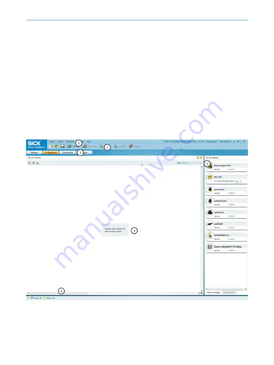
User interface
Figure 44: Software controls
1
Menu bar
2
Toolbar
3
Main navigation
4
Working range
5
Device catalog
7
CONFIGURATION
64
O P E R A T I N G I N S T R U C T I O N S | microScan3 Core I/O AIDA
8017784/1ELL/2022-01-21 | SICK
Subject to change without notice