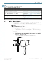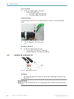
Line
Connect to:
PTFE line from distribution unit (sample gas
inlet)
Lower part of analyzer, to enclosure duct
“Inlet”
PTFE line sample gas outlet
Lower part of analyzer, to enclosure duct “Out‐
let”
Sample gas outlet
b
Discharge the sample gas outlet in a suitable environment.
b
The sample gas output must be open against the ambient pressure.
WARNING
The exhaust gases are toxic
b
Dispose of the exhaust gases in a suitable manner.
2.11.3
Electrical installation of analyzer
1
Power voltage connection at terminal
strip
2
Signal connections (I/O)
3
Distributor board with Ethernet for MPR
(option), Modbus, service interface (LAN)
Electric line
Connect to:
Power supply from distribution unit
Terminal strip near On/Off switch
Signal lines to/from distribution unit
See attached circuit diagram
Analyzer grounding
On the right of the enclosure outside
MPR for remote maintenance via Ethernet
(option)
In analyzer upper part on distribution board
RJ45 connection 0X5 “LAN”
PC with SOPAS ET (Ethernet) (option)
Modbus
NOTE
The green coiled network line in the analyzer bottom part serves as spare line and does
not have to be connected.
INSTALLATION
2
8017324/15A2/V6-0/2019-10 | SICK
T E C H N I C A L I N F O R M A T I O N | MARSIC200
35
Subject to change without notice


