5.4
Mounting the device
Aligning the device with viewing window to object
The device must be aligned in consideration of the field of view (
) and the application circumstances (
see "Installation requirements",
).
Mounting the device
Perform one of the following steps:
•
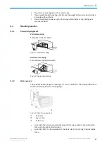
Mount the device on a customer-supplied mounting bracket using M5 screws.
Screw the screws no more than 5 mm into the tapped blind holes or sliding nuts.
°
To do this, either use the tapped blind holes in the housing in pairs at the
front or below or use the two M5 sliding nuts in the lateral slots.
•
Attach the separately-ordered, optional SICK mounting bracket (e.g. part number
2042902) to the device using the two sliding nuts.
5.5
Mounting the read cycle sensor (optional)
If the device is triggered by means of an external trigger sensor, the trigger sensor must
be mounted close to the device.
a
a
b
a < b
b
b < a
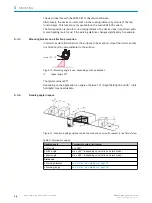
Figure 14: Positioning an external trigger sensor for the read cycle (mounting example)
The mounting location of the device depends on the distance a of the codes from the
front object edge. Depending on the application, mount the device so that codes on
objects of different sizes can be read completely during the evaluation time window
(reading interval).
MOUNTING
5
8022502/15NT/2020-02-11 | SICK
O P E R A T I N G I N S T R U C T I O N S | Lector621
31
Subject to change without notice

