Chapter
3
Operating Instructions
Laser measurement sensor LD-MRS
54
©
SICK AG · Germany · All rights reserved · Subject to change without notice
8012948/ZMQ0/2017-06-09
Product description
•
IP 67: type
μ
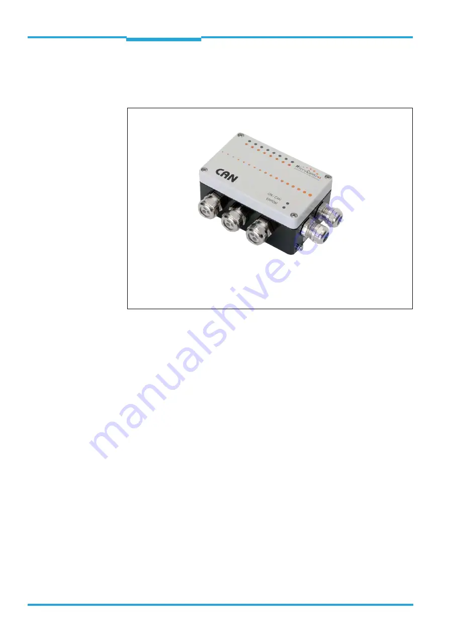
CAN.8.dio-BOX (Part No. 6041328), small metal housing with seven
threaded holes for cable glands (4 x M16, 3 x M20) and 36 terminals.
An additional set (Part No. 6043917) consisting of 5 cable glands/2 blind covers (in
metal) is available.
The address range of 1 to 127 is available in the CAN bus. By default, the LD-MRS has the
address 1. The transmission rate of 500 kBit/s is fixed by the LD-MRS and needs to be set
for the two CAN modules.
When a cable is used to connect to the LD-MRS (Part No. 2050647 (2 m (6.56 ft))/Part No.
2050648 (8 m (26.2 ft)) in maximum configuration, both CAN modules are connected to
the end of the bus via the 9-pin D-sub connector. The required terminals are created using
the internal switches of each module. If only one module is connected to the LD-MRS, the
9-pin D-sub connector (Part No. 6042511) offers an integrated termination resistor for one
end of the bus as an adapter.
3.11
Status indicators and controls
The LD-MRS does not have any status indicators like LEDs, and it does not have any controls
like switches. The device is configured for measurement mode by means of commands in
messages or using the "SICK LaserView Customer Edition" visualization tool via the Ethernet
interface and is switched to measuring mode. Configuration for field monitoring is per-
formed using the SOPAS-ET.
Fig. 3-37:
μ
CAN.8.dio-BOX module
(The image may differ)
Only operate the CAN module when the housing is closed!


