COMMISSIONING AND OPERATION
5
8024534 / 16UW / 2020-02-26
Operating Instructions | InspectorP Rack Fine Positioning
35
Subject to change without notice
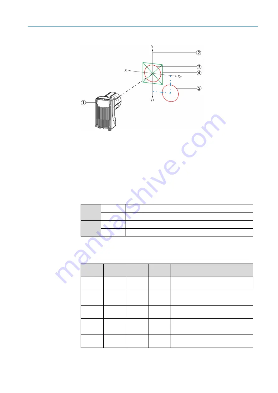
(1)
Device
(2)
Coordinate system, for determining the location of the positioning mark
(3)
Positioning mark in the middle of the target region (X = 0 µm, Y = 0 µm)
(4)
Target region
(5)
Positioning mark below the target region and to the right (X = 14,000 µm, Y = 15,000 µm)
5.4.6
Control via digital inputs and digital outputs
Digital input sensor 1 activates and deactivates continuous measurement. The
“Sensor2” digital input can be used to switch between the Single and Double deep
modes.
Sensor 1
1
Continuous measurement is switched on.
0
Continuous measurement is switched off.
Sensor 2
1
Double deep mode is activated.
0
Single deep mode is activated.
The IN/OUT 3 – IN/OUT 6 digital outputs give information about the current position
of the positioning mark. In evaluation mode 1 – 8, all outputs in the following table are
possible. In evaluation mode 9 – 13, the device only outputs via the digital outputs
whether the positioning mark is located within the target region.
IN/OUT 3
(up)
IN/OUT 4
(down)
IN/OUT 5
(right)
IN/OUT 6
(left)
Position of the positioning mark relative to
the target region
1
1
1
1
The positioning mark is located within the
target region.
0
1
1
1
The positioning mark is located above the
target region.
1
0
1
1
The positioning mark is located below the
target region.
1
1
0
1
The positioning mark is located to the right
of the target region.
1
1
1
0
The positioning mark is located to the left of
the target region.
Figure 9: Interpretation of the position correction values


