5
ELECTRICAL INSTALLATION
50
8011325/18IM/2020-07-02|SICK
O P E R A T I N G I N S T R U C T I O N S | ICR880/890
Subject to change without notice
5.2
Electrical connections and cables
NOTE
Prerequisites for enclosure rating IP64
At the time of delivery, provide all electrical connections of the camera and the illumina-
tion with corresponding protective caps.
To maintain enclosure rating IP 64, all electrical connections unused during operation
must be provided with protective caps. The plug connectors must be firmly fastened or
engaged to the connections used.
The same applies for the EMC requirements (ESD) according to CE.
The protective caps have the following colors:
•
M12 plug connectors: yellow (male connectors) and black (female connectors)
•
RJ-45 connections: gray, fastened to the device with a catch strap (cannot get lost)
•
Voltage supply: black
WARNING
Radio interference may occur in residential areas
Radio interference may result when used in residential areas.
Measures
▸
Only use the camera systems in industrial environments.
5.2.1
Electrical connections on the ICD880/890 camera
Standard system
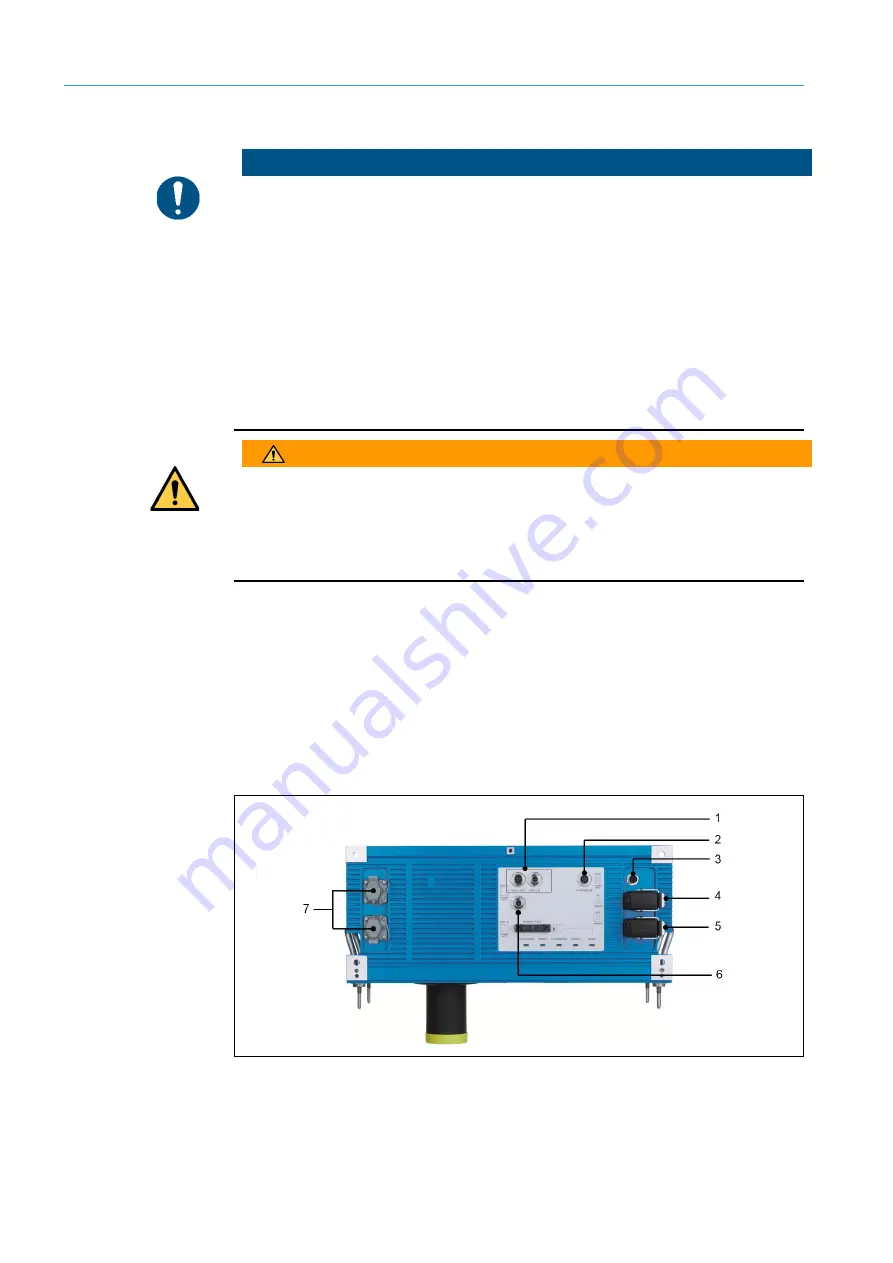
The electrical connections on the underside of the camera system consist of:
•
Seven M12 plug connectors mounted on the camera housing (on and next to the
aperture)
•
Two Harting plug connectors for the voltage supply as well as
•
Two RJ-45 connections (enclosure rating IP 67) for Gbit Ethernet.
Fig. 37: Camera – position of the electrical connections (standard system)


