


Function
Description
3
Load the current settings on the camera that work for the inspection of the
current article from the currently selected camera into the article configuration.
The previous settings in the article will be overwritten.
NOTE
When setting up a new article or making adjustments to an existing
article, the
Fetch Camera Config
action must be performed for each camera. The
article must then be saved. If multiple cameras are involved in the inspection
of the article, the settings of all cameras must be loaded into the article config‐
uration via this path once the article setup is complete. After that, the status
indicator for the article-camera combination must be green.
4
Delete the current parameters on the active camera.
7.5.4.2.4
Adjust configuration
The following procedure is recommended for adjusting the configuration:
b
Select the desired article and camera.
b
Transfer the configuration to the camera. This is done automatically at the start
of an inspection run. This can also be done without an inspection by opening
Set
Plan to Camera
. The button can be found on the page in the
Test Article
menu.
b
Clear the existing camera configuration on the camera using the
Camera
page,
Clear Camera Config
action.
b
Adjust the article-specific camera settings and verify the settings by means of test
runs.
b
Transfer the current parameters from the camera to the article configuration using
the
Fetch Config from Camera
action.
b
Save the article.
7.5.4.3
Block
page
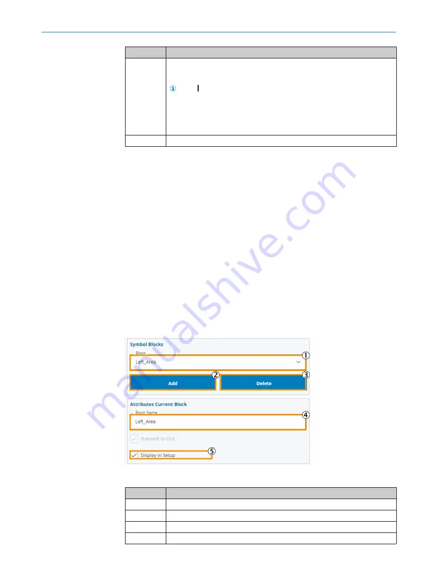
The purpose of the blocks in the schematic diagram is to indicate in which area of the
inspection object defects were found.
Blocks can be created and configured using the parameters described below.
Figure 38: Block menu page
Function
Description
1
Currently selected block.
2
Add new block.
3
Delete block.
4
Input field for name assignment.
7
OPERATION
44
O P E R A T I N G I N S T R U C T I O N S | FOS-HVS
8027445/V1-0/2022-06-15 | SICK
Subject to change without notice


