


27
8015675/1EEU/2021-12| SICK
O P E R A TI N G I N S T R UC TI O N S | Flow-X
Subject to change without notice
INSTALLATION
4
4.3.7
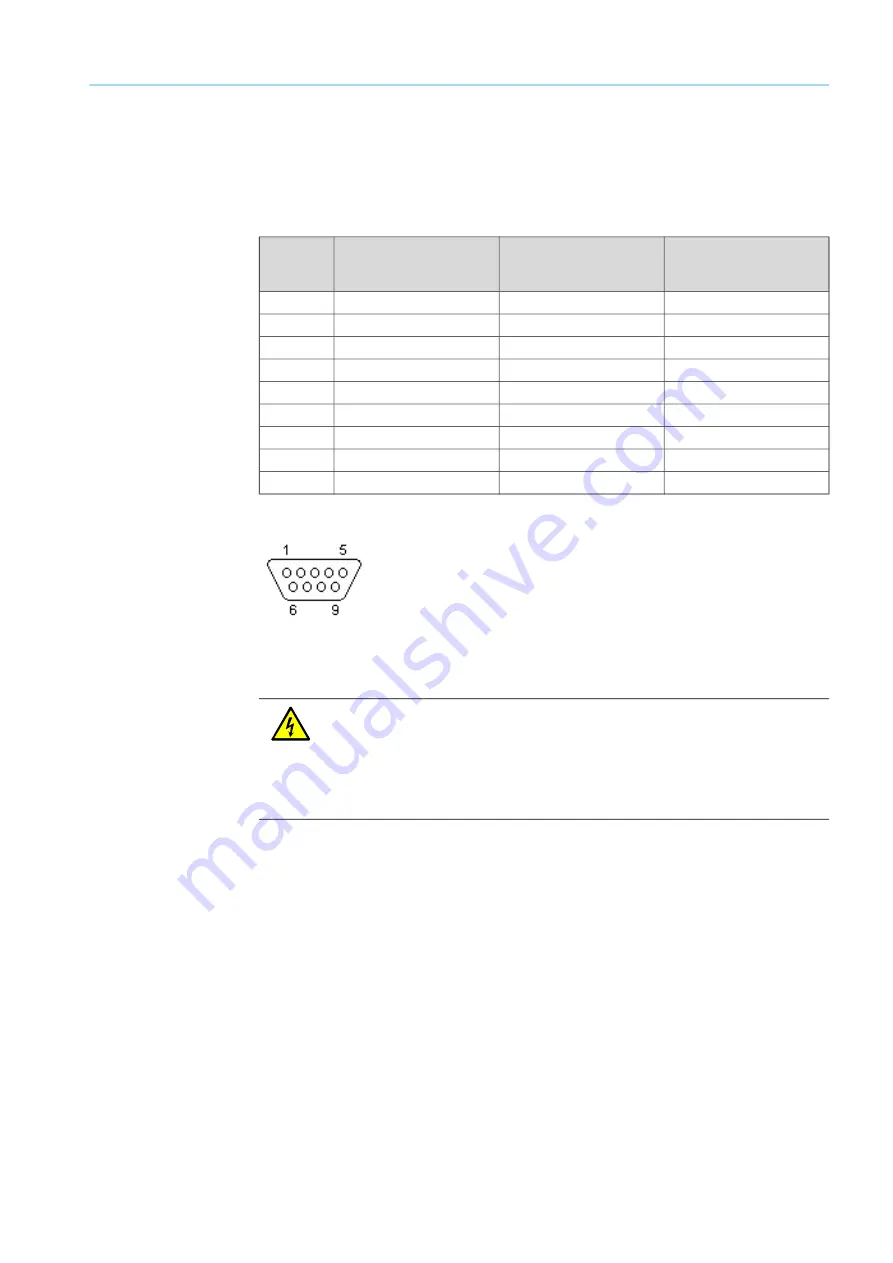
9-pin D-sub connection port (serial communication)
These connection ports are only available on the Flow-X/P (Com 1 to 3) and Flow-X/C (Com
3) flow computers. These serve to connect to the serial COM ports of the display module.
The connection ports of the Flow-X/P or Flow-X/C are plugs. The connecting line must have
a socket. COM3 is implemented as RS485 on Flow-X/C.
Fig. 21: 9-pin D-sub connection ports
4.3.8
Ethernet
The Flow-X/P and Flow-X/C flow computers have two standard RJ45 Ethernet connections.
Whether these Ethernet connectors can be used for communication or not depends on the
software configuration. If the corresponding flow module operates autonomously, i.e. not in
a multi-module configuration, the Ethernet ports can be used to communicate with the flow
module. This also applies when the flow module is the “first” flow computer in a multi-
module configuration. “First” means the first in the software program, this does not
necessarily correspond to the physical position within the rack.
Pin
COM1
RS-232 only
COM2 / COM3
RS-232 / RS485 (2-wire) /
RS485 ( 4-wire)
COM3 Flow-X/C
RS-232/RS-485
1
RX
2
RX
Rx+
3
Tx
TX / Sig- / Tx-
TX/ Sig- /Tx-
4
- / Sig+ / Tx+
5
0 V
6
7
RTS
-/Sig+ / Tx+
8
CTS
9
Table 8: 9-pin D-sub connector pin connections for Flow-X/P
WARNING:
The device may only then be connected to the power supply when ALL of the other
desired cables and plugs are connected to the device.
A plug or cable may only be disconnected from the device when the voltage supply to
the device has been disconnected beforehand.
Connecting plugs or cables while the device is in operation can cause irreparable
damage to the electronics. Corresponding defects are excluded from a warranty claim.


