


41
8024493/AE00/V1-0/2020-09| SICK
O P E R A T I N G I N S T R U C T I O N S | DUSTHUNTER SP100 Ex-2K
Subject to change without notice
PROJECT PLANNING
4
4.2.3
Project checklist
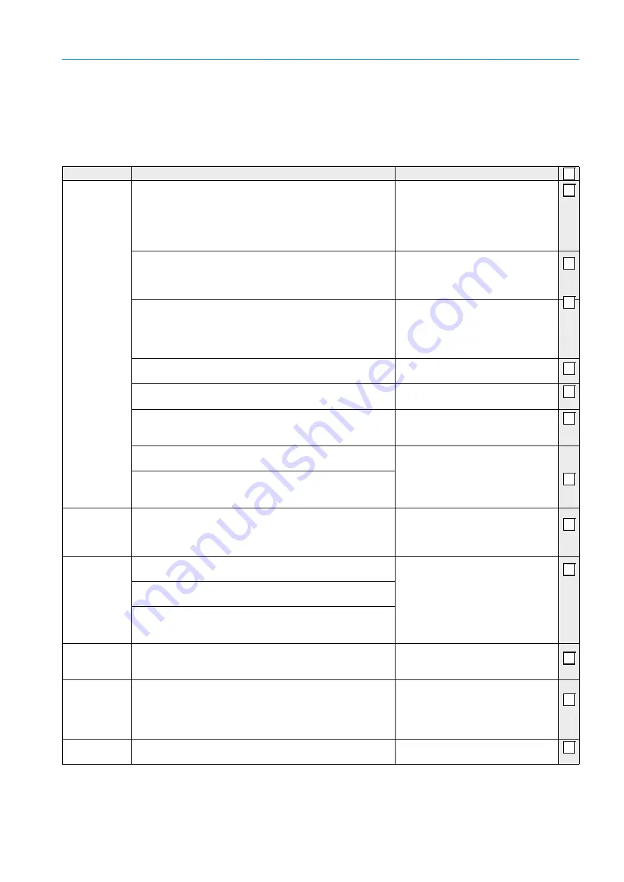
The following Table provides an overview of project planning work necessary as prerequisite
for trouble-free assembly and subsequent device functionality. You can use this table as a
checklist and tick off the completed steps.
Table 10: Project checklist
Task
Requirements
Work step
Determine
measuring and
installation
locations for
device
components
Inlet and outlet piping in accordance with DIN EN 13284-1
– Inlet at least 5 × d
h
(hydraulic diameter)
– Outlet at least 3 x d
h
– Distance from stack opening at least 5 × d
h
For round and square ducts: d
h
= duct diameter
For rectangular ducts: d
h
= 4 × A (surface) ÷ U (circumference)
Follow specifications for new systems
Select best possible location for existing
systems.
For too short inlet/outlet paths:
Inlet path > outlet path
Homogeneous flow distribution / representative dust distribution
– Whenever possible, no deflections, cross-section variations,
feed and drain lines, flaps or fittings in the area of the inlet and
outlet paths
If conditions cannot be ensured:
Define flow profile in accordance with
DIN EN 13284-1 and select best
possible location.
Sender/receiver unit fitting location and alignment
– No vertical mounting on horizontal or inclined ducts, max.
angle of the measuring axis to the horizontal 45
°
– Observe alignment to flow direction (
receiver unit to the duct geometry”, page 62
)
Select best possible location
Provide information on duct direction.
Accessibility, accident prevention
– Device components must be safely accessible
Provide platforms or pedestals as
required.
Installation free of vibrations
– Acceleration < 1 g
Take suitable measures
to eliminate/reduce vibrations.
Ambient conditions
– Limit values according to Technical Data (
)
If necessary, provide weather protection
(
), enclose
or lag components.
Consider lines and hoses at the installation site
(
see “Connection line with Ex-Plug-Connector”, page 126
Observe line and hose lengths.
Select the best possible location,
potential equalization line must allow
removing the sender/receiver from the
duct when connected.
Observe the application illustration (
DUSTHUNTER SP100 Ex-2K”, page 33
) with regard to the
installation locations.
Purge gas
Determine type
and quantity
Suitable purge gas in compliance with application-specific require-
ments for explosion protection.
– Whenever possible, low amount of dust, no oil, moisture,
corrosive gases
Provide purge gas supply.
Work steps,
.
Select device
components:
Measuring
device
Nominal length of sender/receiver unit and flange with pipe
according to duct diameter, duct wall thickness with insulation
Select components according to
configuration (
sender/receiver unit”, page 36
; If
necessary, plan additional measures for
mounting flange with tube (
the flange with tube”, page 45
Sender/receiver unit type (up to 220 °C or up to 400 °C)
depending on gas temperature in duct
Measuring probe material depending on gas composition in the
duct
– For corrosive gases, measuring probe made of Hastelloy
Select control
unit
Power supply and communication options based on the intended
system integration
Select components according to the
Configuration Table (
MCUDH Ex-3K control unit”, page 37
Plan calibration
openings
Easy and safe access, no mutual interference of calibration probe
and measuring system
Provide platforms or pedestals as
required.
Plan sufficient distance between
measuring and calibration level
(approx. 500 mm)
Plan the voltage
supply
Supply voltage and power requirements according to Technical
Data (
see “Technical data”, page 118
Plan adequate line cross-sections and
fuses