


- 12 -
Before removing or installing any of these devices including CPU, DIMMs, Add-On
Cards, Cables, please make sure to unplug the onboard power connector.
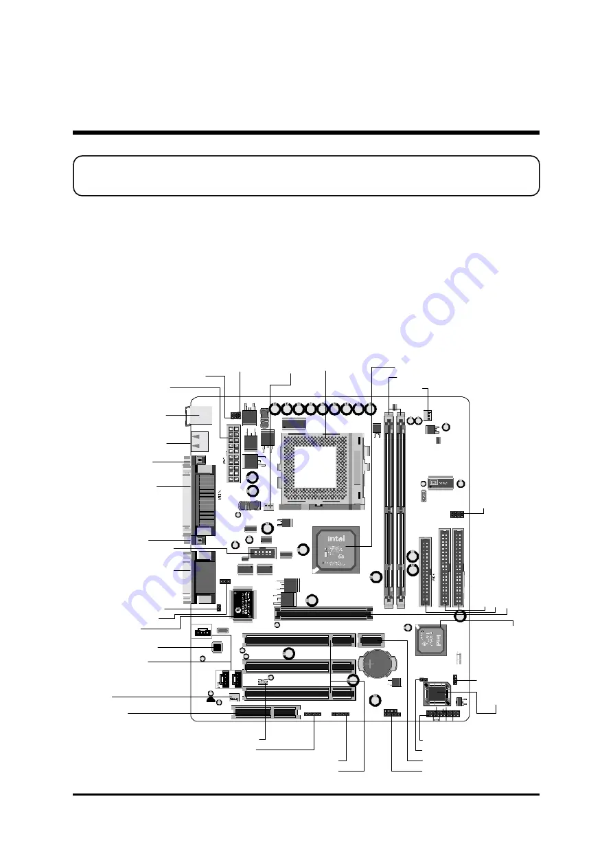
This section outlines how to install and configure your ME21 mainboard. Refer to the
following mainboard layout to help you to identify various jumpers, connectors, slots, and
ports. Then follow these steps designed to guide you through a quick and correct installa-
tion of your system.
3.1 Step-by-Step Installation
Accessories of ME21
3 HARDWARE INSTALLATION
USB1
KBMS1
J P8
J P7
AJ 1
JP
5
J1
JP
3
1
1-
2
3-
4
J 6
J 17
IR
Front Panel
Au di o
J 27
1
1
1
IDE 2
IDE 1
1
1
1
D IM M 1 D IM M 2
CNR1
FA N3
1
J 13
1
J 5
1
J 2
1
J 7
J P14
1
1
GD
7
52
32
D
HS4
8
GD
7
52
32
D
HS4
8
1
J P9
FA N1
1
FA N2
1
J 9
1
JP
1
1
JP
1
2
1
1
1
J 23
1
+ -
+ -
+ -
RST
EPMI
GLED
POW_BTN
SPKR
KEYLOCK
PWRLED
PG
A3
7
0
P
an
aso
n
ic
CR2
03
2
3V
JA
P
A
N
1
in
b
o
n
d
Three PCI Slots
O
ne 4
x A
G
P Sl
ot
In
te
l 828
01B
A
C
hi
ps
et
CNR Slot
SOCKET 370
FAN3
Two USB Connectors
Two DIMM Sockets
FAN2
Connector -
JP9
COM2
K/B & PS/2 Mouse Power-On setting -
JP14
PS/2
USB K/B Wake-Up setting -
JP14
Clear Password -
J7
Chassic intrusion -
J9
Extended two USB connector -
J6
Parallel Connector
VGA Connector
Intel 82815 Chipset
Serial Port
Connector (COM1)
On Board CODEC
Line-In/Line-Out/Mic-In
Game/MIDI Connectors
Onboard Audio
Connectors
Wake on LAN -
J13
BIOS Top Block Lock -
J5
Front Panel Connector -
J23
Cl
ea
r C
M
O
S -
J2
FSB
Sp
eed
C
on
fig
Set
tin
g -
J
1,
JP
3,
JP
5
IR Connector -
J17
L-OUT & MIC-IN Connectors header -
J27
Fl
oppy
C
onne
ct
or
Pr
og
ra
m
m
abl
e 2M
b
Fl
as
h EEP
RO
M
PS/2 Keyboard/Mouse
Connectors
I/O Controller
Tw
o E-
ID
E C
on
nec
to
rs
FAN1
ATX Power Connector
One Riser Support Slot


