911-439 Rev. G 5/99
Page: 1 of 4
WATER WIZARD
TM
HAND PUMP MODEL 150
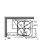
The procedure outlined below is for new installations. To install
the spout there
must
be 2½"
[6.35 cm]
clearance from the template centerline to any interference
behind the unit (back wall) and there
must
be 4¾"
[12.06 cm]
from the centerline to any
interference to the left side of the unit
(see template)
. If the Wizard is to replace an existing hand
pump, modifications to the existing hole may be required. Use the template to determine if the
trim cover will cover an existing hole after modifications. In most installations there are
limitations on space. Use of a hole saw allows the easiest and most precise method to make the
cut out.
1.
Determine the position and check under the counter for adequate space to mount the pump. Make
certain there is sufficient clearance to rotate the spout when installing. Also, if mounted in a flip galley,
check for proper clearance in both positions for the pump and tubing. Mark layout lines in-line with the
center of the drain, and 2¼"
[5.72 cm]
from the outer edge of the sink rim. The ¼"
[6.35 mm]
clearance
will allow cleaning between the trim cover and the sink rim.
2.
Cut the template
(Page: 3)
out around the "edge of trim cover." Position the template over the layout
lines and hold in place with tape. Mark (pilot drill) the position of the four 1¾"
[4.44 cm]
holes.
3.
Use a 1¾"
[4.44 cm]
hole saw to cut the four holes. Trim out the remaining material to attain the cut-out
shown on the template
(bold line)
.
The trim cover may not cover the hole if enlarged past the size
shown.
4.
Place the pump in the cut-out and square it to the sink. Squaring up the pump is easier if the trim
cover is placed in position,
but DO NOT snap it in place!
Mark the four mounting holes and
remove the pump before drilling small pilot holes for
#
6 hardware
*
. If using a power screwdriver,
pilot holes may not be necessary. If installing into an existing hole, simply install the supplied
screws into the existing holes.
5.
On the water line between the tank and pump a water strainer is recommend. To protect the pump
a 50 mesh screen
(or finer)
is necessary, such as the SHURflo Potable Water Strainer
#
170-061-XX
*
supplied with after market pump
#
150-001-00
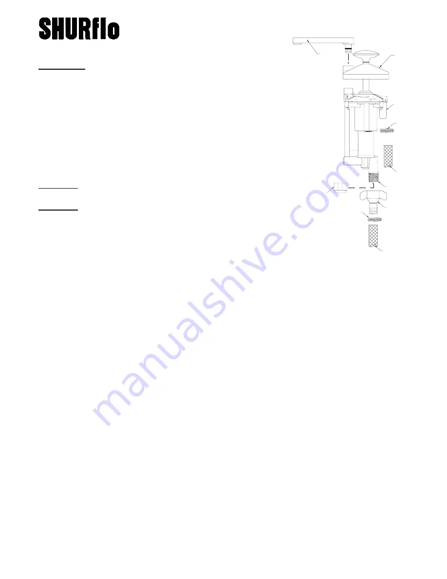
3/8"[10mm]
TANK
1/2" - 14
THREAD
REGULATED
CITY WATER
SEALING
CAP
POTABLE
WATER
FITTING
*
*
*
SPOUT
INLET
TRIM COVER
*
FEATURES
••••
Delivers Water in both stroking directions.
••••
Retrofits into most existing hand pump installations.
••••
"Twist of the Wrist" Hands-Free operation with city water.
••••
Easy winterizing and sanitizing.
••••
FDA materials.
••••
All corrosion resistant materials.
••••
Parts supplied with aftermarket pump, model #150-001-00:
(1) Swivel Barb 1/2" Hose Fitting
#
8-161-00
(2) Hose Clamps
(4)
#
6 Screws
(1) Sealing Cap
READ ALL INSTRUCTIONS BEFORE STARTING
READ ALL INSTRUCTIONS BEFORE STARTING
READ ALL INSTRUCTIONS BEFORE STARTING
READ ALL INSTRUCTIONS BEFORE STARTING THE INSTALLATION
THE INSTALLATION
THE INSTALLATION
THE INSTALLATION
CAUTION: DO NOT freeze
with water in pump. Refer to page 2 for
Winterizing instructions.
CAUTION: DO NOT
snap the square trim cover to the pump until the
unit is correctly located and screwed into position.
NOTE:
To remove trim plate, slip screwdriver into slot on plate, and
gently
pry up on both sides.


