manualshive.com logo in svg
background image

ENGLISH

ENGLISH

15

14

7

1

2

3

5

6

8

9 10 11

12

FIGURE 4

4

18

13

16 17

15

19

U4S Receiver

5

15

14

18

13

16 17

17

18

16

19

15

7

1

2

3

5

6

8

9 10 11

12

4

7

1

2

3

6

8

4

U4D Receiver

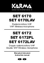
U4S & U4D RECEIVER CONTROLS & CONNECTORS (FIGURE 4)

1. MENU Button. Press this button to access the main display menu.

2. SELECT Button. Press this button to choose or execute a displayed value or

function.

3. RF Level Indicators: Five LEDs per RF antenna channel glow to indicate RF sig-

nal strength. The more LEDs that glow, the stronger the received signal. If none
of these LEDs glow, no signal is being received

4. Audio Level Indicators: These seven LEDs glow to indicate audio signal

strength. Green indicates normal operation. Amber indicates approaching over-
load condition. Red indicates excessively high audio levels. (Clipping occurs
within 4–6 dB when the red LEDs glow).

5. Programmable Display. Displays group and channel number, frequency, squelch

level, system name, transmitter battery power level, and display lock on/off status.

6. + Button: Press this button to scroll display forward.

7. – Button: Press this button to scroll display backward.

8. Audio Output Control: Adjusts receiver output level to match input level require-

ments of a mixer or amplifier. Normally, this control is set fully clockwise.

9. Headphone Monitor Volume Control: Rotate this knob to the right to increase

headphone volume; rotate it to the left to decrease headphone volume.

NOTE: If you are using a Model U4S Receiver, press the Headphone Volume
Control knob to turn the monitor on or off.

If you are using a Model U4D Receiver, press the Headphone Volume Control
knob once to select Receiver 1 or twice to select Receiver 2, depending on which
section you wish to monitor.

10. Headphone Monitor Status: These LEDs glow yellow when the headphone

monitor circuit is turned on or off.

NOTE: The Tone Key feature is present only on the receiver output. As a result,
you may hear an occasional “pop” through the headphones when the transmitter
is turned on or off.

11. Headphone Input Connector: Plug headphones into this 1/4–inch connector to

monitor receiver audio.

12. POWER On/Off Switch: Turns the receiver on and off.

13. Power Input Connector: Accepts power directly from any 90 to 230 VAC, 50/60

Hz power source.

14. Power Output Connector: Provides 90 to 230 VAC, 50/60 Hz power to additional

equipment. It can be used to link multiple receivers or to power the Shure UA840
Antenna Distribution System.

15. Antenna Input Connectors: BNC-type connectors provide connection to the

supplied antennas or to coaxial cable used with a distribution amplifier or remote
antennas.

CAUTION: To avoid damage to equipment, make sure any equipment connected
to the antenna inputs can tolerate 12 VDC power.

16. HIGH Z (Unbalanced) Output Connector: 1/4 inch phone jack provides unbal-

anced auxiliary level (high-impedance) output.

17. Mic/Line Slide Switch: Controls output of balanced XLR connector. It can be set

for microphone or line-level (microphone level = line level – 30 dB)).

18. LOW Z (Balanced) Output Connector: XLR connector provides balanced low-

impedance mic level or line-level output.

19. Networking Interface: 25–pin “D” connector provides future electronic interface

to computers and other equipment via accessory interface box.

8

9

Содержание U Series

Страница 1: ...ed The Sound of Professionals Worldwide Shure Brothers Incorporated 222 Hartrey Avenue Evanston Illinois 60202 3696 Phone 847 866 2200 Fax 847 866 2279 In Europe Phone 49 7131 72140 Fax 49 7131 721414 Internationally Phone 847 866 2200 Fax 847 866 2585 UHF User s Guide ...

Страница 2: ...cking the Receiver Display 20 Unlocking the Receiver Display 20 TRANSMITTER SETUP 21 Transmitter Battery Installation 21 Checking TransmitterBatteries 22 Connecting a Lavalier Microphone or Instrument Cable to the U1 Transmitter 23 PROGRAMMING THE TRANSMITTER 23 ChangingTransmitterGroup ChannelSettings 23 Locking the Power Switch in the ON Position 26 Cancelling the Power On Lock Function 26 Activ...

Страница 3: ...hrough your receiver Dual RF Level Meters The U4S and U4D receivers have two RF meters one for each antenna The dual meters indicate received signal strength at each antenna and make it easier to identify and troubleshoot dead spots Audio Metering Each receiver includes a seven segment audio meter that lets you monitor audio level and helps optimize transmitter gain setting TransmitterDisplay Show...

Страница 4: ...nd off 5 On Off LED Glows green when the U1 is turned on 6 Belt Clip Allows the transmitter to be easily worn on a belt waistband or guitar strap 7 MODE Button Selects the parameter Group or Channel you wish to change 8 SET Button Changes transmitter Group and Channel settings Also used with the MODE button to lock power on and to lock the frequency and channel setting 9 Audio Gain Control Allows ...

Страница 5: ...l keys 5 ON OFF Switch Turns transmitter power on and off 6 Antenna Helical antenna is attached to the end of the U2 transmitter The anten na can be replaced in the field by a qualified technician 7 Battery Compartment Contains two 1 5 V AA batteries Duracell MN1500 rec ommended 8 MODE Button Selects the parameter Group or Channel you wish to change 9 SET Button Changes transmitter Group and Chann...

Страница 6: ...tor on or off If you are using a Model U4D Receiver press the Headphone Volume Control knob once to select Receiver 1 or twice to select Receiver 2 depending on which section you wish to monitor 10 Headphone Monitor Status These LEDs glow yellow when the headphone monitor circuit is turned on or off NOTE The Tone Key feature is present only on the receiver output As a result you may hear an occasi...

Страница 7: ... ADAPTER BULKHEAD ADAPTER 2 Connect the supplied antenna cables to the receiver and the bulkhead adapters as shown in Figure 7 RECEIVER TOP VIEW FIGURE 7 ANTENNA CABLE ANTENNA CABLE NOTE Shure recommends connecting the bulkhead adapter and antenna cables before mounting the receiver in a rack Once the receiver is in the rack it is more diffi cult to insert the bulkhead adapters and connect the ant...

Страница 8: ...with a UA830 Active Remote Antenna Kit VIEWING CURRENT RECEIVER SETTINGS To view current settings on the receiver display proceed as follows 1 Turn the receiver on by pressing upper half of the POWER switch 2 Press either the button or the button on the receiver front panel to scroll through the current settings PROGRAMMING THE RECEIVER You can change the receiver Group Channel setting the operati...

Страница 9: ...to the original setting See Figure 15 FIGURE 15 NOTE If more than 20 seconds of inactivity elapse the display will return to the original settings Changing Receiver Frequency Setting 1 Press the MENU button The MENU display will appear as shown in Figure 16 FIGURE 16 2 Press either the or button to reach the SET FREQ display shown in Figure 17 FIGURE 17 3 Press the SELECT button The current operat...

Страница 10: ...ue until you have spelled out the entire name 6 When the new name has been completely entered press the MENU button SAVE will appear followed by YES NO Press the button to save the new name and return to the Group Channel TV display Press the button to make more changes See Figure 24 FIGURE 24 NOTE If more than 20 seconds of inactivity elapse the display will return to the original settings Changi...

Страница 11: ...5 5 97 8 6 0 98 1 6 5 98 4 7 0 98 7 7 5 99 0 8 0 99 3 8 5 99 6 9 0 99 9 9 5 100 2 Minimum 10 Open U4S and U4D squelch values differ slightly Specifications subject to change without notice 5 Once you have reached the desired squelch level press the MENU button SAVE will appear followed by YES NO as shown in Figure 28 Press the button to make more changes or press to save the new squelch setting an...

Страница 12: ...eventing the user from changing any settings TRANSMITTER SETUP Transmitter Battery Installation Figure 34 1 Make sure the transmitter power ON OFF switch is in the OFF position 2 Open the transmitter battery compartment as follows U1 Transmitter Squeeze the two tabs on either side of the transmitter and flip the battery cover down U2 Transmitter Unscrew the battery cover and slide it down FIGURE 3...

Страница 13: ...wn the microprocessor will turn off RF power the Tone key and the display Connecting a Lavalier Microphone or Instrument Cable to the U1 Transmitter Figure 36 1 Plug the microphone cable or instrument cable into the transmitter input connector 2 Attachthelavaliermicrophonetoyourtie shirtorcollar Ifyouareusingaheadset put the headset on 3 If an instrument adapter cable is used attach the other end ...

Страница 14: ...t increment mode if more than 20 seconds of inactivity elapse the display will return to the original settings 5 Press the MODE button again so that only the Channel number is displayed as shown in Figure 40 FIGURE 40 6 Press the SET button to change the Channel setting as shown in Figure 41 FIGURE 41 7 Press the MODE button again so that the new Group and Channel numbers are both displayed NOTE O...

Страница 15: ...e Transmit ter Power On Lock function can also be cacelled by removing the batteries FIGURE 43 Activating the Frequency Lock Function The Frequency Lock function prevents accidental frequency changes and is par ticularly useful in preventing accidental or unauthorized changes The lock function is retained in memory even if the transmitter is turned off and the batteries removed To activate the Fre...

Страница 16: ...ushing this knob selects the receiver section you wish to monitor 8 Begin speaking or playing your instrument Rotate the OUTPUT LEVEL knob as necessary to achieve desired receiver output levels NOTE If the red PEAK LEDs on the receiver do not flicker during the loudest sounds or if they are always on the transmitter gain may need to be increased or decreased Refer to Adjusting the Transmitter Audi...

Страница 17: ...OTE The factory preset 6 dB should match most applications Before chang ing the audio input level try adjusting the transmitter gain see Figure 47 The U1 body pack transmitter has an attenuator switch that allows you to set the au dio input level for different types of applications Use one of the following three set tings according to the type of input source you are using 0 dB fully counterclockw...

Страница 18: ...a connection s Makesureatleastoneantennaisinthelineofsightofthetransmit ter If necessary reduce the distance between transmitter and re ceiver Problem Solution No receiver sound RFandAudioLevel meter LEDs glow ing Turn up the receiver audio output Level control Check for proper connection between receiver and microphone mixer Talk into the microphone and observe the receiver audio level LEDs If th...

Страница 19: ... 6 Diversity A Analog Output 2 kΩ 1 4 V 7 Network In terrupt Digital Input Not Applicable 1 4 V 8 Network In terrupt Digital Output Busy Not Applicable 1 4 V 9 Serial Data Output Digital Output Not Applicable 1 4 V 10 Serial Data Input Digital Input Not Applicable 1 4 V 11 5V Not Applicable 5 V 12 5V Not Applicable 5 V 13 5V indicates unit is dual channel Not Applicable 1 4 V 14 Audio Meter Analog...

Отзывы: