DRO-550 Construction Guide (rev. 2)
1
S
HUMA
T
ECH
DRO-550 Construction Guide
Страница 1: ...DRO 550 Construction Guide rev 2 1 SHUMATECH DRO 550 Construction Guide ...
Страница 2: ...o and Program Switch 10 Step 9 Board Rework 12 Step 10 Program Software and Troubleshoot 12 Fabricate the Enclosure 13 Step 1 Machine the Front Panel 13 Step 2 Machine the Rear Panel 15 Step 3 Drill the USB Hole 16 Step 4 Install the Standoffs 17 Step 5 Install the Connectors 18 Step 6 Attach Overlay 20 Cables Construction 20 Assemble the PCB Step 1 Parts Inventory After receiving your power buy k...
Страница 3: ...raid impregnated with flux that when pressed against a solder connection with a soldering iron wicks the solder up into braid It is invaluable for desoldering a bad connection or removing excess solder Antistatic Wrist Strap Since we are working with static sensitive components you should wear an antistatic wrist strap at all times while handling the boards and components You should also try to wo...
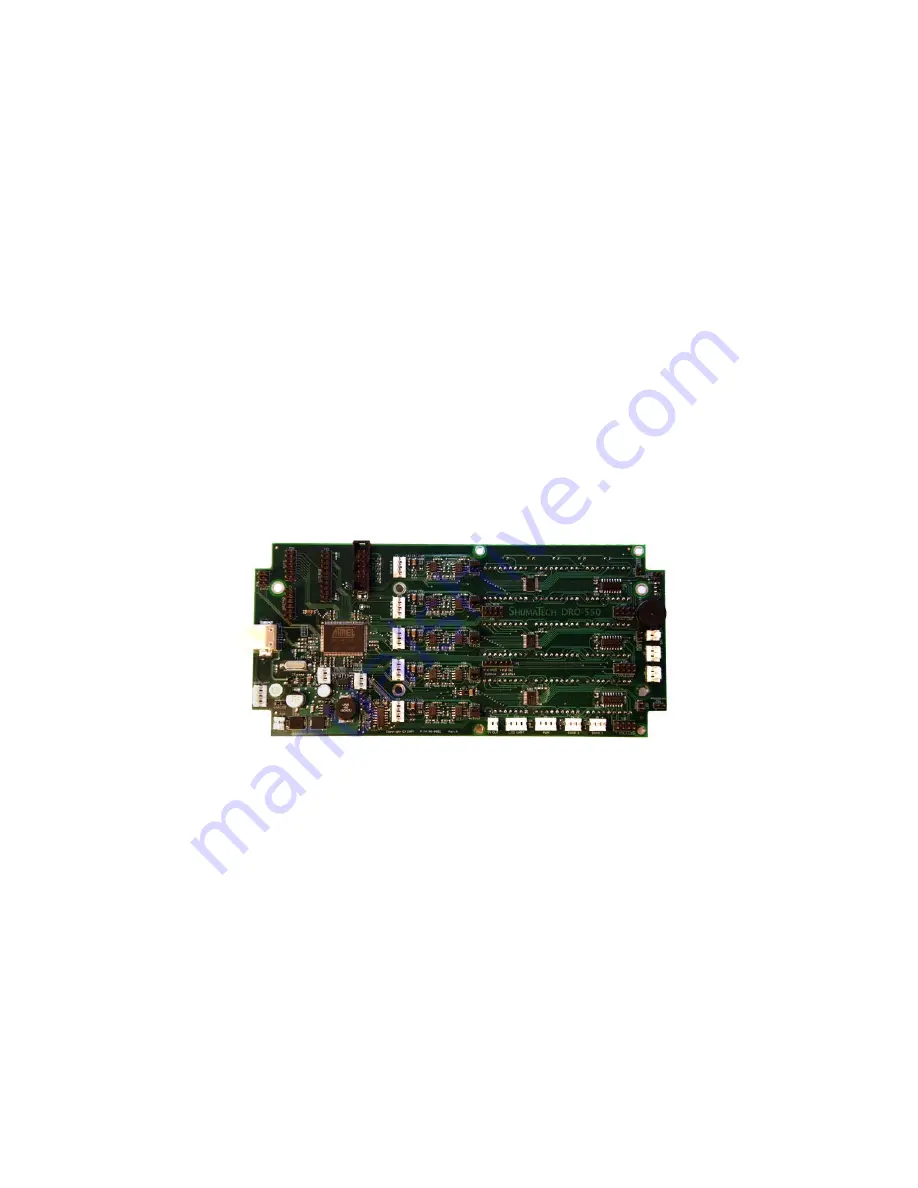
Страница 4: ...orientation Reference the picture on the left The red arrows point out the orientation marks for components that must be placed on the board in a certain way The orientation marks are small lines or dots that are marked on the components There are also small white dots on the printed circuit board that indicate the correct position of the orientation marks with respect to the board For each red ar...
Страница 5: ... rows and they are located on the right side of the board The left IC is the column driver and it should have its orientation mark in the upper left The right IC is the segment driver for the row and its orientation mark should be to the left If any of the orientations described above are not correct then DO NOT POWER ON THE BOARD You will likely damage the component and possibly even the power su...
Страница 6: ... is constructed out of four layers with the power planes existing on the two internal layers Since there is no way to directly inspect these layers we will electrically check them for shorts using 5 test points Get your multimeter and set it to measure resistance The table below lists the ten possible combinations of the five power planes We will measure the resistance between each possible ...
Страница 7: ...han the ones directly beside it You can probe either directly on the shiny part of the capacitor or on the small round via directly above it The 1 5V test point is the upper right round pad on the J30 header The pad is directly below the V in the 1 5V label Black Probe Red Probe Ground 5V Ground 3 3V Ground 1 8V Ground 1 5V 5V 3 3V 5V 1 8V 5V 1 5V 3 3V 1 8V 3 3V 1 5V 1 8V 1 5V Step 4 Smoke Test Th...
Страница 8: ...ased or made yourself Plug the power supply into the internal power cable but leave the AC side UNPLUGGED Connect the internal power cable onto the J13 header you just soldered in With the board in front of you plug the AC into the wall and look and smell for signs of overheating If you notice any IMMEDIATELY unplug the AC from the wall and seek assistance If everything looks and smells good then ...
Страница 9: ...tance When the SAM BA dialog box comes up press cancel to close it We will program the software into the DRO 550 later after we finish assembly of the DRO 550 Step 6 Solder Headers There are a number of through hole headers that we must solder onto the board five 2x2 pin headers five 4 pin headers five 3 pin headers and two 2 pin headers We already soldered one of the 2 pin headers in place at J13...
Страница 10: ...m the front It is a lot of trouble to desolder a display if you get it wrong The five indicators LEDs are soldered into the DS1 DS5 positions above the 7 segment displays Be careful to orient the LEDs properly into the holes The SHORTER leg of the LED is inserted into the SQUARE pad on the board If an LED doesn t work when you power up the board then you probably inserted it backwards Look at the ...
Страница 11: ...rface mount a slightly different technique is required from the other through hole parts Notice that there are four shiny pads for the switch with a white square in the middle that shows the proper position of the switch Apply a little pool of solder to the upper left hand pad With your solder iron in one hand and holding the switch in the other hand place the switch within the white box while hea...
Страница 12: ...pin 1 on J21 DBG UART Pin 1 is the square pad on top and is also highlighted with an arrow To affect the fix solder a wire between the two locations The C37 side of the wire can either be soldered on the via or on the side of the capacitor itself The J21 side can be soldered anywhere on the square pad That s all there is to it Your RS 232 port is now good to go Step 10 Program Software and Trouble...
Страница 13: ... shiny look If the problem persists then it could be a failed component on the board If the problem is with a few individual segments then it could be a bad 7 segment display If the problem is the same segment in all six columns then it could be the sink driver IC for that row If the problem is an entire digit then it could be the source driver IC for that row If the whole row is out then it could...
Страница 14: ...ng the plastic None of the drill holes in the drawing are critical You can do fine using the closet nominal drill size that is greater than the called out diameter For example the 0 469 12mm diameter called out for the tact switch buttons can be drilled with a 1 2 diameter drill bit The overlay will cover up any overage or mistakes so don t worry about precision here For the display cut outs use a...
Страница 15: ...ever you like The drawing below shows one possible layout for the rear panel This layout is based on the DRO 350 rear panel so if you already have a DRO 350 case with the original layout then you can just add the extra connector holes that you need Just be careful to stay away from the standoffs that are on the inside DRO 550 Rear Panel Drawing ...
Страница 16: ...e DRO 550 and to interface the DRO with a PC to control its functions The hole for the USB exits the case on the keypad side of the front panel This is the right side when viewing the DRO from the front Drill a hole for the USB connector at the position shown in the drawing below DRO 550 Side Panel Drawing ...
Страница 17: ...l to stop as soon as the front of the tap hits the bottom of the post hole otherwise you will strip the threads If you do don t worry since you can just epoxy the standoffs in place just as well The hex standoffs are made of aluminum and have a 6 32 male thread on one end and a 6 32 female thread on the other end The male thread is slightly too long for the plastic posts so you must grind or cut a...
Страница 18: ...st easily done with a small hand tap After tapping mount the scale connectors to the back panel with the 4 40 x 1 2 screws The edge finder and tachometer connectors are 3 5mm stereo jacks The DRO 550 supports up to two of each Remove the nuts included with the connectors and mount them on the rear panel If MTA plugs are used on the other end of the cables then they must not be installed until afte...
Страница 19: ...r listed in the bill of materials is a snap in type that is simply pushed into the hole drilled into the back panel Depending on the tolerances of the hole you may need to put a few drops of hot glue or epoxy to assure that the connector does not pull out of the hole when the power cord is removed ...
Страница 20: ...with X Y and Z designations for mills and one with X Z1 and Z2 designations for lathes The overlays are best installed by masking the front of the completed enclosure with masking tape and spraying on a layer of adhesive such as Super77 onto the front of the enclosure The overlay can then be pressed into place onto the front of the enclosure IMPORTANT Do not forget to remove the plastic protective...
Страница 21: ...d as shown in the following picture The tip is 5V to ensure that the auxiliary device is not energized until the plug is fully inserted The RS 232 interface is used for both programming the DRO 550 and for interfacing it to a PC The cable is wired as indicated in the table The connector is a 9 pin female d sub connector RS 232 Signal PCB Pin J18 Female DB 9 Pin Tx 1 3 Rx 2 2 Ground 3 5 ...
Страница 22: ...y is shorted To make your own cables you need to buy four pin mini DIN plugs PS 2 keyboard and mouse plugs are mini DIN as well the only difference being that they have six pins instead of the four used by the DRO 550 Mouser carries these plugs stock no 171 2604 for a reasonable price You can also check the other electronics distributors such as Digi Key Allied Newark etc I would recommend the sol...
Страница 23: ... don t want a big puddle of solder but you do want enough to make a solid connection to the wire on the cables Next strip the end of each wire and attach it to each pad by holding the wire against the pad with one hand and touching the pad with the solder iron with the other hand Look at the diagram of the scale jack below to figure out which wire to solder to which pad The most important thing he...