background image

Содержание SA 400 minifloppy

Страница 1: ...SA400 CQ m minifloppyTM DisketteStorageDrive 2 C J ...

Страница 2: ...SA400 CQ m minifloppyTM DisketteStorageDrive 2 C J Copyright 1977 Shugart Associates ...

Страница 3: ...ho purchase it as an OEM device It contains the timing electrical and mechanical specifications recommended formats and circuitry necessary to interface it to a host controller formatter For maintenance information reference the SA400 Service Manual P N 54096 Minifloppy minidiskette and ministreaker are Shugart Associates trademarks ...

Страница 4: ...Operations 3 1 Power Sequencing 3 2 Drive Selection 3 3 Motor On 3 4 Track Accessing 3 4 1 Step Out 3 4 2 Step In 3 5 Read Operation 3 6 Write Operation 3 7 Sequence of Events 3 8 Multiplex Option 3 8 1 Drive Selection Electrical Interface 4 1 Signal Interface 4 1 1 Input Lines 4 1 1 1 Input Line Terminations 4 1 1 2 Drive Select 1 3 4 1 1 3 Motor On 4 1 1 4 Direction Select 4 1 1 5 Step 4 1 1 6 W...

Страница 5: ...Marks 7 3 1 3 CRC 7 3 1 4 Optional Soft Sectored Recording Format 7 3 2 Hard Sectored Recording Format Application Notes 8 1 Data Separator 8 1 1 True FM Data Separator 8 2 Read Data Circuits 8 3 CRC Generating and Checking Circuitry 8 4 Index Sector and Ready Logic 8 5 Error Detection and Correction 8 5 1 Write Error 8 5 2 Read Error 8 5 3 Seek Error Operation Procedures 9 1 Minidiskette Loading ...

Страница 6: ...6 SA400 Drive Dimensions 17 Data Pattern 18 Bit Cell 19 Byte 20 Data Bytes 21 Track Format 18 Records Track 22 ID Address Mark 23 Data Address Mark 24 Deleted Data Address Mark 25 Soft Sectored Formats 26 Hard Sectored Formats 27 Data Separator Functional Diagram 28 Data Separator Timing Diagram 29 True Data Separator 30 Register Controls and AM Detection 31 Data and Clock Registers 32 AM Timing 3...

Страница 7: ...FIGURE 1 SA400 MINIFLOPPY DRIVE ...

Страница 8: ...nded ferrite ceramic read write head as the SA800 uses AC power requirements have been eliminated through the use of a DC servo controlled spindle drive motor The drive is also equipped with an interface which allows upward expansion of the units within the system and future system enhancements with the large floppy drive Applications for the minifloppy drive include word processing and text editi...

Страница 9: ...PI 5162 FCI 48 TPI 35 1 542 in 3 916 em 2 250 in 5 715 cm 1 Spec ification Summary average settling time Head Load Time Disc Motor Start Time Rotational Speed Recording Density inside track Flux Density Track Density Tracks Inside Track Radius Outside Track Radius Index Encoding Method Media Requirements 1 1 Capacity Unformatted per disk 109 4K bytes per track 3125 bytes Formatted Reference Sectio...

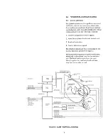
Страница 10: ...own in figure 2 The head positioning actuator positions the read write head to the desired track on the minidisk ette The head load actuator loads the mini diskette against the read write head and data may then be recorded or read WRITE ROTECT IN C WRITE PROTECT COM READ DATA DRIVE SELECT WRITE DATA WRITE GATE WRITE PROTECT DR IVE SELECT STEP DIRECTION SELECT DRIVE SELECT 13 LINES TRACK 00 INDEX S...

Страница 11: ...er track The drive control electronics issues the second step pulse needed per track 2 5 Read Write Head The SA400 R W head is a single element glass bonded ferrite ceramic head with straddle erase elements to provide erased areas between data tracks Thus normal interchange tolerances between media and drives will not degrade the signal to nOlse Lilio and lnsures minidiskette interchangeability Th...

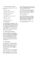
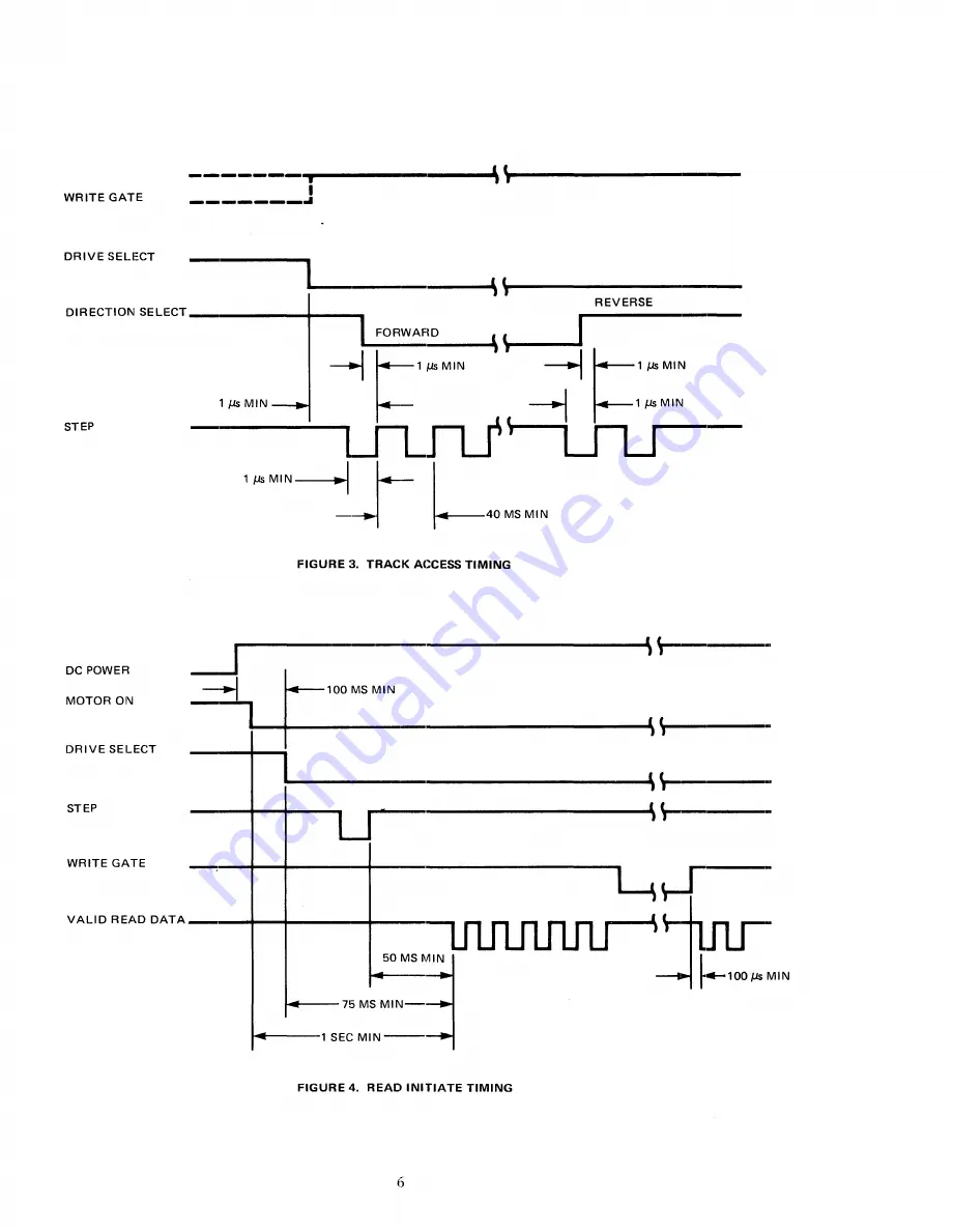
Страница 12: ...ted Under normal operation the Drive Select line will load the R W head against the mini diskette enabling contact of the R W head with the media and will also light a LED on the front plate 3 3 Motor On In order for the host system to read or write data the DC drive motor must be turned on This is accomplished by activating the line Motor On A one 1 second delay must be introduced after activatin...

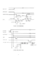
Страница 13: ...RECTION SELECT __ FORWAFlD I 1 r 1 ruMIN l MIN r I l MIN _r_ 40MSMIN STEP FIGURE 3 TRACK ACCESS TIMING j DC POWER MOTOR ON DRIVE SELECT I J J 100MS MIN L _ STEP _ _ WRITE GATE VALID READ DATA t_ ll _ t4 75MSMIN 1 SEC MIN FIGURE 4 READ INITIATE TIMING 6 ...

Страница 14: ...at the R W head position has stabilized prior to reading The timing of Read Data is shown in figure 5 3 6 Write Operation Writing data to the SA400 is accomplished by a Activating the Drive Select line 7 b Activating the Write Gate line c Pulsing the Write Data line with the data to be written The timing relationships reqUired to initiate a write data sequence are shown in Figure 6 These timing sp...

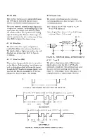
Страница 15: ...ION B LEADING EDGE OF BIT MAY BE 400 ns FROM ITS NOMINAL POSITION FIGURE 5 READ SIGNAL TIMING 1 1 p __ J J DRIVE SELECT _ 1 J f 75 MS MIN_ STEP WRITE GA TE WRITE DATA r 4 50 MSMIN 14 _ 1 SEC MIN II __ FIGURE 6 WRITE INnlATE TIMING WRITE DATA I 250 ns MIN I 8 00j 1s 40 ns I 2100nSMAX FIGURE 7 WRITE DATA TIMING 8 4 00j 1s I 20 ns r ...

Страница 16: ...ER ON 1 S EC MAX VALID INDEX SECTOR OUTPUT o 500nSMAX DIRECTION SELECT I i STEP WRITE GATE WRITE DATA VALID READ DATA 1 1J Js MIN ir I i 50 MS MIN 14 75 MS MIN _ __ I J SEeMIN 1 J 1 00 J Js MIN lflJ 104 75 MS MIN I 1SEC MIN FIGURE 8 GENERAL CONTROL AND DATA TIMING REQUIREMENTS 9 ...

Страница 17: ...THIS PAGE INTENTIONALLY LEFT BLANK 10 ...

Страница 18: ...to the host output via interface connector PI J 1 4 1 1 Input Lines The input signals are of 3 types those intended to be multiplexed in a multiple drive system those which will perform the multiplexing and Motor Control The input signals to be multiplexed are 1 Direction Select 2 Step 3 Write Data 4 Write Gate The input signals which are intended to do the multiplexing are 1 Drive Select 1 2 Driv...

Страница 19: ...IVE SELECT 2 13 12 DRIVE SELECT 3 14 15 MOTOR ON 17 4_ 16 DIRECTION SELECT 19 4 18 STEP 21 4_ 20 WRITE DATA 23 4_ 22 WRITE GATE 25 1 24 TRACK 00 27 26 WRITE PROTECT 29 28 READ DATA 30 5 VDC J2 X 4 3 _ 5 RETURN L 12 VDC r 1 2 X 12 RETURN DC GND m AC GND TWISTED PAIR FRAME GND FIGURE 9 INTERFACE CONNECTIONS 12 ...

Страница 20: ... shorted 13 The program shunt IC location 1F positions DSl DS2 and DS3 are to be used to select which Drive Select line will active the I O lines for a unique drive As an example if the user wants the first drive on the interface to be address 1 he must cut program shunt positions DS2 and DS3 and leave DSl intact The program shunt is AMP part number 435704 6 The shunt positions can be cut using AM...

Страница 21: ... current through the R W head to be reversed thereby writ ing a data bit This line is enabled by Write Gate being active Refer to figure 7 for timings 4 1 2 Output Lines The output control lines have the following electrical specifications Refer to figure 10 for the recommended circuit True Logical Zero Vout O OV to OAV lout 48 rna max False Logical On Vout 2 5V to 5 25V open collector lout 250 J ...

Страница 22: ...logical zero level for the active state Reference figure 5 for the timing and bit shift tolerance within normal media variations 4 1 2 4 Write Protect This interface signal is provided by the drive to give the user an indication when a Write Protected Diskette is installed The signal is logical zero level when it is protected Under normal operation the drive will in hibit writing with a protected ...

Страница 23: ...THIS PAGE INTENTIONALLY LEFT BLANK 16 ...

Страница 24: ... connector The dimensions for this connector are shown in figure 13 The pins are numbered 1 through 34 with the even numbered pins on the component side of the PCB and the odd numbered pins on the non component side Pin 2 is located on the end of the PCB connector closest to the corner and is labeled 2 A key slot is provided between pins 4 and 6 for optional connector keying The recommended connec...

Страница 25: ...ide 5 3 Frame Grounding The SA400 must be frame grounded to the host system to insure proper operation If the frame of FIGURE 14 J2 CONNECTOR the drive is not fastened directly to the frame of the host system with a good AC ground a wire from the system AC frame ground must be con nl cted to the SA400 For this purpose a faston tab is provided on the drive near the motor con trol PCB where a faston...

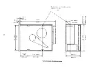
Страница 26: ...l Dimensions Reference figure 16 for dimensions of the SA400 6 2 Mounting As shipped from the factory the SA400 is capable of being mounted in one of the following positions 19 1 Top loading 2 Front loading mounted upright mounted vertical with door opening left or right mounted horizontal with PCB up Do not horizontal mount with PCB down ...

Страница 27: ...I rl I I I I I I I I I I I I I I I I I I I I I I I L_ _ J I I I J LJ 86 02 4X I I 2 18 05 I I 3 25 ro J 8 25 07 r I I I I oj I I I I i I I I I I I d J riL 7 92 05 3 12 02 8X I I J 1 t 1 I I I 1 8 00 max 19 881 I I Lf J I I r cIr1 1 87 02 4X 4 74 05 01 0 I J I 1 0 1 1 N o FIGURE 16 SA400 DRIVE DIMENSIONS ...

Страница 28: ... PRESENT I r 41J I _ BIT CELL j 8IJSEC FIGURE 18 BIT CELL 7 2 Byte A Byte when referring to serialdate being written onto or read from the disk drive is defined as eight 8 consecutive bit cells The most significant bit cell is defined as bit cell 0 and the least significant bit cell is defined as bit cell 7 When reference is made to a specific data bit i e data bit 3 it is with respect to the corr...

Страница 29: ...d G4 shortened The SAI04 minidiskette is the media to be used in soft sectoring 7 3 1 1 Gaps Each field on a track is separated from adjacent fields by a number of bytes These areas are referred to as gaps and are provided to allow the updating of one field without affecting adjacent fields At the end of each gap except Gap 4 are four bytes of zeros which are used for synchroniz ing the data separ...

Страница 30: ...D I I DATA FIELD RECORD DATA GAP RECORD GAP 2 RECORD 1 18 BYTES 2 2 10 ADDRESS MARK 10 RECORD 1 GAP 1 INDEX GAP 20 BYTES SYNC BYTES HEX 00 GAP4 PRE INDEX 103 BYTES HEX FF GAP BYTES HEX FF DATA FIELD RECORD 18 N W GAP BYTES HEX FF SYNC BYTES HEX 00 WRITE GATE OFF HEX FF GAP BYTES HEX FF SYNC BYTES HEX 00 6 BYTES d 4 BYTES WRITE GATE TURN ON FOR UPDATE OF NEXT DATA FIEU B Y T E 16BYTES l 4BYTES WRIT...

Страница 31: ... to identify the beginning of ID and Data Fields and to synchronize the deserializing circuitry with the first byte of each field Address Mark bytes are unique from all other data bytes in that certain bit cells do not contain a clock bit all other data bytes have clock bits in every bit cell There are three different types of Address Marks used Each of these is used to identify different types of...

Страница 32: ...REPRESENTATION OF DATA BITS o CLOCK BITS o o o HEXADECIMAL REPRESENTATION OF DATA BITS CLOCK BITS FIGURE 23 DATA ADDRESS MARK C C C TCELL I TCELL TCELL C C D D BIT CELL 7 14 DELETED DA TA ADDRESS MARK BYTE I BINARY REPRESENTATION OF DATA BITS o o o CLOCK BITS o o o HEXADECIMAL REPRESENTATION OF DATA BITS CLOCK BITS FIGURE 24 DELETED DATA ADDRESS MARK 25 ...

Страница 33: ...please contact the factory 7 3 2 Hard Sectored Recording Format In this format the using system may record up to 16 or 10 sectors records per track Each track is started by a physical index pulse and each sector is started by a physical sector pulse This type of recording is called hard sectoring Figure 26 illustrates the hard sectored formats The SAl05 or SAl07 minidiskette is to be used for thes...

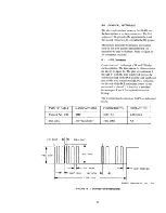
Страница 34: ... the remainder of the bit cell time either 2 1 lS or 2 lS In discussing the data separator circuit figure 27 initially assume all circuits are reset inactive and that the READ DATA line contains what is shown in figure 28 With both SSI and SS2 off Clk Window is active The first Read Data pulse will be allowed through AND A2 and out as Sep Clk Sep Clk is sent out onto the interface line and to LI S...

Страница 35: ...SS2 DATA WINDOW i O jJs r y S l1 D Q FF1 FI I C Q I FIGURE 27 DATA SEPARATOR FUNCTIONAL DIAGRAM 8 o o I I I IlL I I I I U lf I __ _ I I o B I 1 I 0 L L _ I I IC D IC l1 SEP DATA 0 Ff 1 Q 552 LONG 551 SHORT READ DATA ClK WII JDOW HEX EQUIV 81 NARY EQUI V DATA WINDOW 5EP ClK FIGURE 28 DATA SEPARATOR TIMING DIAGRAM 28 ...

Страница 36: ...and 29 data patterns correspond exactly to that of an address mark If not address mark is detected the CRC register and synchronization circuitry is reset during the bit ring 7 A one s catching latch is used to detect a pulse on the separated data line from the diskette drive and the leading edge of the separated clock line from the diskette drive is used to shift the state of the latch into a shi...

Страница 37: ...GLE SHOT TIMES INCLUDES THE DATA BIT PULSE WIDTH TIMING DIAGRAM GAP 2 1 _ DATA AM 1 DATA C e C e D e D D D D e e D e D e e l lEAD DATA _ 11 __ 1 L __ 1 L__ IL n_ L IL _ _ L__ I L __ L_IL I_ II L _ JIL _ 5EP DATA SEP elK L1 5S1 FF1 FF2 FF3 5S2 FIGURE 29 TRUE DATA SEPARATOR 30 ...

Страница 38: ...CK SU I I I I C eA ATWDATAl Hij S D nl T W I DELETED DATA AM d DATA AM 1 1 _ lOAM 4 4 4 0 AM DETECTED I I BR 7 tJ I IK 01 CLOCK BIT ENABLE BIT RING CLOCK TER r I BIT IRING f Ilru tL 1 RESET AM Bit Ring State 2 0 0 0 0 3 1 000 4 1 1 00 5 1 1 1 0 6 1 1 1 1 7 0 11 t f 0100 1 1 111 010011 i I FIGURE 30 REGISTER CONTROLS AND AM DETECTION ...

Страница 39: ...I I I I I I I I I I I I I I 7 6 5 4 3 2 1 0 READ DATA I 1 L I D 4 BIT SHIFT REG I D 4 BIT SHIFT REG D 4 BIT SHIFT REG I D 4 BIT SHIFT REG r 7 6 5 4 3 2 1 0 7 6 5 4 r 3 2 1 0 D Q r I I I n L J I I I r IDAM J DATA AM I I u DATA BIT LOAD SHIFT CLOCK BIT SHIFT DATA REG SHIFT CLOCK REG W N FIGURE 31 DATA AND CLOCK REGISTERS ...

Страница 40: ...RO S OUTOF PHASE AM DETECTED BIT RING SHIFT DATA REG SHIFT CLOCK REG 6 1 7 I 0 1 1 1 2 1 3 1 4 1 5 1 6 1 7 1 0 1 1 I 2 1 3 _ In n n n n n n n n n n nL __ ____ In n n n nL __ I I I f I II I I I I I I I I I I I I I I I I 2 I 2 I 2 _2 2 3 4 I 5 I 6 I 7 I 0 I 1 I 2 I I _ In n n n n n n n n n n n n _ ____n n n n n n rL1l n n n n n _ FIGURE 32 AM TIMING ...

Страница 41: ...on if Drive Select goes active between Sector 16 or 10 and Index Drive Select to Ready delay is less than 60 ms and greater than 40 ms if the diskette is within 80 of speed The Ready will go inactive at the loss of either Drive Select or 15 or 24 ms after the diskette drops below 80 of speed 34 8 5 Error Detection and Correction 8 5 1 Write Error If an error occurs during a write operation it will...

Страница 42: ...T 0 I I CRC BIT 16 CRC BIT 1 DATA BIT 15 DATA BIT SHIFT DATA REG W til ENABLE BIT RING FIGURE 33 CRC GENERATION CRC 1 CRC 2 CRC 3 CRC 4 CRC 5 CRC 6 I CRC 7 CRC 8 eRC 9 CRC10 CRC 11 CRC 12 CRC 13 CRC 14 g g j DATA CORRECT ...

Страница 43: ...EDIA SS3 15 MS FOR SA105 MEDIA 25 M FOR SA107 MEDIA SS4 ilJ s DELAY o 2J o INDEX WINDOW MOTOR START TIME OUT J t P U UP TO SPEED P U t 01 P U LOSS OF SPEED J DETECT b 1 diJ L L J MTR ON ANY DRIVE SELECT INDEX SECTOR W 0 FIGURE 34 INDEX SECTOR SEPARATOR AND READY CIRCUIT ...

Страница 44: ... SS3 QB READY QD INDEX CASE 2 DRIVE SELECT SSl SS2 OB READY 00 INDEX CASE 3 DRIVE SELECT SSl SS2 QB 00 INDEX _____ rL IL Jl L_ IIL IL _ a _ IL _ _ I r i l ___________ 1 If ________ InL INDEX DETECTED __________________ L NDEX DETECTED J NO INDEX DETECTED FIGURE 35 INDEX SECTOR TIMING 37 ...

Страница 45: ...FIGURE 36 SA400 WITH SA4400 CONTROLER 38 ...

Страница 46: ... on the minidiskette and minifloppy drive 9 1 Minidiskette Loading Figure 37 shows the proper method of loading a minidiskette in the SA400 To load the diskette open the door on the front panel insert the diskette with label towards the door handle and close handle A mechanical interlock prevents door closure without proper media insertion thus eliminating media damage FIGURE 37 LOADING SA400 39 ...

Страница 47: ...e on the plastic jacket with a lead pencil or ball point pen Use a felt tip pen 5 Heat and contamination from a carelessly dropped ash can damage the disk 6 Do not expose diskette to heat or sunlight 7 Do not touch or attempt to clean the disk surface Abrasions may cause loss of stored data 9 3 Write Protect Feature The SAl 04 105 minidiskettes have the capability of being write protected A write ...

Страница 48: ... ShUgart Associates 435 Oakmead Parkway Sunnyvale California 94086 Telephone 408 733 0100 TWX 910 339 9355 SHUGART SUVL 54102 2 9 78 PRINTED IN U SoA ...

Отзывы:

Похожие инструкции для SA 400 minifloppy