64
5. Parameters
5.1. Parameter definition
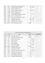
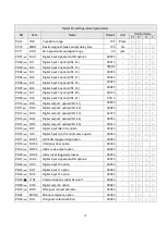
The parameters of SDE servo drive are classified into the basic parameters, gain/ filters, expansion
parameters and I/O parameters. When an advance adjustment is required, change the parameter PA42
setting to make the expansion parameters valid.
Here are some notes for reading of parameter manual.
1. Parameter classification
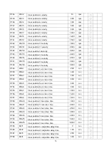
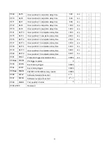
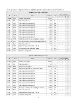
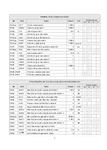
There is a parameter list which is classified due to the functions for user to consult conveniently.
Refer to section 5.2 for more details.
2. Special symbol of parameter sign
(
★
)
denotes the setting is valid by power off once and power on again.
(
■
)
denotes the setting is vanished once power off.
(
▲)
denotes the invalid change as the Servo ON activated.
There are 2 ways to make Servo ON disabled.
(1) Turn off the SON DI signal.
(2) Set the PD16 as 1 and the drive would be at Servo OFF state. But remember to recover it after
the completion of modification.
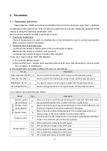
Group classification according to different functions is listed below.
Group
Description
Basic parameter (No PA
□□
)
Used to perform the position control. Please set this parameter group.
Gain, filter (No PB
□□
)
Used to perform the manual-gain tuning. Please set this parameter group.
Expansion
(No PC
□□
)
As speed or torque control is required, please set this parameter group.
I/O settings (No PD
□□
)
Used to change the states of I/O signal. Please set this parameter group.
The control mode is described as follows.
Mode
Sign
Description
S
in
gl
e m
od
e
Position control
(terminal input)
Pt
Drive runs motor to reach the goal according to the external commands which
are received through the CN1 and are in the form of pulse trains.
Position control
(inner register)
Pr
Drive runs motor to reach the goal according to the inner commands which are
from inner 8 registers that could be switched by DI signals.
Speed control
S
Drive runs motor to attain the target speed. The command type which is an
analog voltage or the inner registers could be switched by DI.
Torque control
T
The drive receives the commands to run the motor to generate the demanded
torque. The command source is the analog voltage.
Mode switched
Pt-S
Pt/S is switched mutually via the LOP signal.
Pt-T
Pt/T is switched mutually via the LOP signal.
Pr-S
Pr/S is switched mutually via the LOP signal.
Pr-T
Pr/T is switched mutually via the LOP signal.
S-T
S/T is switched mutually via the LOP signal.
Содержание SDE Series
Страница 13: ...5 1 6 Function block diagram ...
Страница 26: ...18 3 3 3 CN1 pin name list ...
Страница 212: ...204 SDE 075A2U SDE 100A2U 750W 1KW unit mm Dimensions of the servo drive may be revised without prior notice ...
Страница 223: ...215 SME L040 SME L075 SME L100 SME L150 ...
Страница 224: ...216 SME L200 SME L300 SME M100 SME M150 Continuous running range ...
Страница 225: ...217 SME M200 SME M300 NOTE These characteristic plots above are measured in case of 3φ 200 240V power supplied ...
Страница 227: ...219 ...
Страница 231: ...223 4 Wiring example with peripheral equipment CN2 Encoder socket ...
Страница 242: ...234 12 4 Version information Version V1 01 Issue date Aug 2017 Proofreader Yaochou Shu ...

