


124
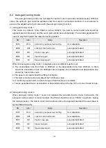
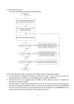
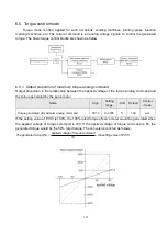
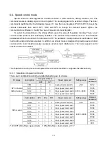
6.2. Auto-gain tuning mode
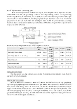
The auto-gain tuning mode can calculate the load to motor inertia ratio instantaneously. With this
value, the optimum gain could be decided under the current mechanical condition. It is convenient to
execute the adjustment of gain value with the auto-gain tuning function.
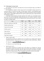
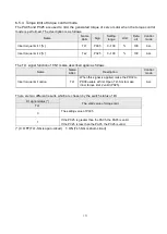
(1) Auto-gain tuning mode 1
This mode is a
default. If the PA02 is set as “0002h”, the load to motor inertia ratio would be
approximated continuously and the servo gain will be set automatically. The variable parameter for
users is only PA03 which the response setting related.
NO.
Abbr.
Name
Operation
PA03
ATUL
Auto-tuning response level setting
User adjustable
PB06
GD1
Load to motor inertia ratio
auto-
approximated
PB07
PG1
Position loop gain
auto-
approximated
PB08
VG1
Speed loop gain
auto-
approximated
PB09
VIC
Speed integral gain
auto-
approximated
When the auto-gain tuning mode 1 is applied, some conditions must be met.
a. The acceleration time from 0rpm to 2000rpm or the deceleration time from 2000rpm to 0rpm
should be 2 seconds or less. If a 3000rpm case is applied, the acceleration and deceleration time
should be 3 seconds or less.
b. The speed command should be 250rpm or higher.
c. The load to motor inertia ratio should be 100 times or less.
d. A machinery system with a violent change of load inertia is not suitable.
e. Torque generated due to acceleration or deceleration should be the 10% or more of rated torque.
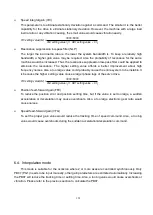
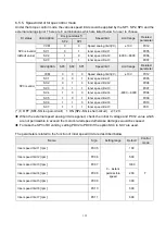
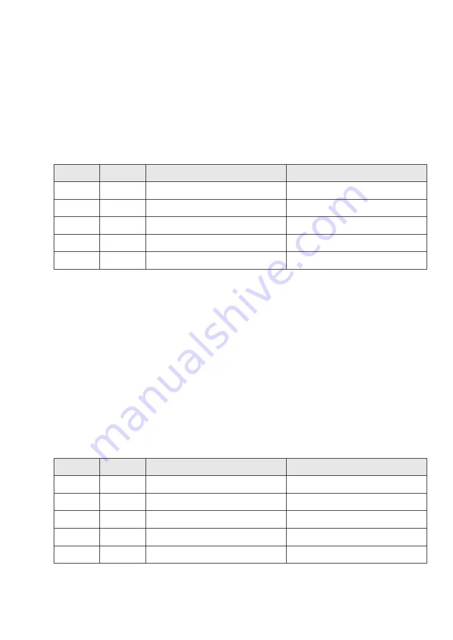
(2) Auto-gain tuning mode 2
When auto-gain tuning mode 1 could not calculate the accurate load to motor inertia ratio, the
auto-
gain tuning mode 2 is recommended. The PA02 should be set as “0003h” to perform. During
the tuning process
,
the load to motor inertia ratio would not be approximated and the users have to
set the PB06 manually.
NO.
Abbr.
Name
Operation
PA03
ATUL
Auto-tuning response level setting
User adjustable
PB06
GD1
Load to motor inertia ratio
User adjustable
PB07
PG1
Position loop gain
auto-
approximated
PB08
VG1
Speed loop gain
auto-
approximated
PB09
VIC
Speed integral gain
auto-
approximated
Содержание SDE Series
Страница 13: ...5 1 6 Function block diagram ...
Страница 26: ...18 3 3 3 CN1 pin name list ...
Страница 212: ...204 SDE 075A2U SDE 100A2U 750W 1KW unit mm Dimensions of the servo drive may be revised without prior notice ...
Страница 223: ...215 SME L040 SME L075 SME L100 SME L150 ...
Страница 224: ...216 SME L200 SME L300 SME M100 SME M150 Continuous running range ...
Страница 225: ...217 SME M200 SME M300 NOTE These characteristic plots above are measured in case of 3φ 200 240V power supplied ...
Страница 227: ...219 ...
Страница 231: ...223 4 Wiring example with peripheral equipment CN2 Encoder socket ...
Страница 242: ...234 12 4 Version information Version V1 01 Issue date Aug 2017 Proofreader Yaochou Shu ...


