


UX-P115U
5 – 9
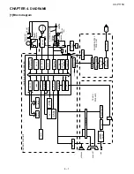
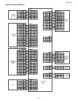
[3] Circuit description of TEL/LIU PWB
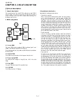
1. TEL/LIU block operational description
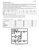
1.1. Block diagram
1.2. Circuit description
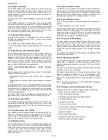
The TEL/LIU PWB is composed of the following 6 blocks.
1. Speech circuit section
2. Dial transmission section
3. Speaker amplifier section
4. Ringer circuit section
5. CI detection circuit
6. Signal/DTMF transmission level & receiving level
1.3. Block description
1. Speech circuit section
• The receiver volume is an electronic volume type, this model is
switched in 3 steps.
2. Dial transmission section
• D.P. transmission: The CML relay is turned on and off for control in
the DP calling system. (Refer to the attached sheet.)
• DTMF transmission: It is formed in the modem, and is output.
3. Speaker amplifier section
• Ringer volume: It is controlled by the combination of the attenuator
value of the LINE DRIVER in the modem and the ringer sending
level sent from the modem.
• Speaker volume: It is controlled by the attenuator value of the LINE
DRIVER in the modem.
4. Ringer circuit section
• The ringer sound is formed in the tone of modem when CI signal is
detected. The amplifier circuit drives the speaker of the main body.
Fig. 5
DAC
LPF
DAC
H
L
CI DETECTOR
SPEAKER
LINE
+24VL
DG
CONTROL PWB
TEL/LIU PWB
RX
TX
TEL MUTE
(H:MUTE)
PC1
Q102
IC100
Q103
IC100
IC100
IC100
IC4
0,1
0,0
1,0
1,1
RTLOOP
ADC
SIN
MIC
/LINE
SELECT
SP OUT
ENABLE
MIC ENABLE
LINE IN ENABLE
LINE OUT ENABLE
0,20,25,30dB
LINE
SELECT
1,1
0,0
1,0
0,+4dB
SOUT
MODEM BLOCK
(CX20438 I/A)
SPKRP
MICP
LINEIN
LINE
OUT
MUTE,0,-6,-12dB
IC3 SCE209
FAX CONTROLLER
DTMFMUTE
RCVOL
SP MUTE
TEL MUTE
CI
CML
MIC MUTE
SPOUT
SP MUTE
(H:MUTE)
TEL IN
RXIN
TXOUT
MIC MUTE
(H:MUTE)
CML
SIGTX
SIGRX
0,6dB
HANDASET
Содержание UX-P115
Страница 60: ...UX P115U 6 7 7 Control PWB parts layout Top side ...
Страница 61: ...UX P115U 6 8 8 Control PWB parts layout Bottom side ...
Страница 63: ...UX P115U 6 10 2 TEL LIU PWB parts layout Top side The TEL LIU PWB of the model employs lead free solder ...
Страница 64: ...UX P115U 6 11 3 TEL LIU PWB parts layout Bottom side The TEL LIU PWB of the model employs lead free solder ...
Страница 66: ...UX P115U 6 13 2 Power supply PWB parts layout Top side 3 Power supply PWB parts layout Bottom side ...
Страница 76: ...UX P115U 8 5 MEMO ...