


UX-P115U
3 – 3
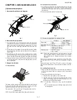
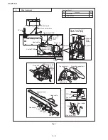
[2] Disassembly and assembly procedures
• This chapter mainly describes the disassembly procedures. For the assembly procedures, reverse the disassembly procedures.
• Easy and simple disassembly/assembly procedures of some parts and units are omitted. For disassembly and assembly of such parts and units,
refer to the Parts List.
• The numbers in the illustration, the parts list and the flowchart in a same section are common to each other.
• To assure reliability of the product, the disassembly and the assembly procedures should be performed carefully and deliberately.
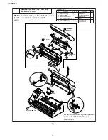
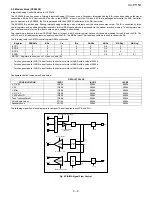
Fig. 1
Bottom plate, PWB's and drive unit
1
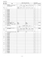
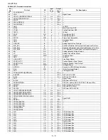
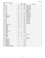
Parts list (Fig. 1)
9
Connector
1
10
TEL/LIU PWB unit
1
11
Connector
6
12
Screw (3x10)
1
13
Hook
1
14
Control PWB unit
1
15
Wire holder PWB
1
16
Screw (3x10)
2
17
Drive unit
1
No.
Part name
Qty
No.
Part name
Qty
1
Mechanism uni
1
2
Screw (3x10)
5
3
Screw
1
4
AC cord earth cable
1
5
Bottom plate
1
6
Hook
1
7
Connector
1
8
Power supply PWB unit
1
Push
2
2
2
5
3
15
15
16
16
17
1
13
6
AC cord
4
7
8
10
9
11
11
14
11
11
11
4
Washer
12
TEL/LIU PWB unit
Power supply PWB unit
Control PWB unit
Bottom plate
Drive unit
Mechanism unit
Содержание UX-P115
Страница 60: ...UX P115U 6 7 7 Control PWB parts layout Top side ...
Страница 61: ...UX P115U 6 8 8 Control PWB parts layout Bottom side ...
Страница 63: ...UX P115U 6 10 2 TEL LIU PWB parts layout Top side The TEL LIU PWB of the model employs lead free solder ...
Страница 64: ...UX P115U 6 11 3 TEL LIU PWB parts layout Bottom side The TEL LIU PWB of the model employs lead free solder ...
Страница 66: ...UX P115U 6 13 2 Power supply PWB parts layout Top side 3 Power supply PWB parts layout Bottom side ...
Страница 76: ...UX P115U 8 5 MEMO ...