background image

MD-MS722/C/W/MS721W

– 1 –

CONTENTS

Page

SAFETY PRECAUTION FOR SERVICE MANUAL (MD-MS722W/MS721W ONLY) ............................................................  2
SPECIFICATIONS .................................................................................................................................................................  3
NAMES OF PARTS ...............................................................................................................................................................  4
OPERATION MANUAL ..........................................................................................................................................................  6
QUICK GUIDE (MD-MS722 ONLY) .......................................................................................................................................  9
DISASSEMBLY ....................................................................................................................................................................  11
INSTALLING THE TOP CABINET .......................................................................................................................................  11
REMOVING AND REINSTALLING THE MAIN PARTS .......................................................................................................  12
ADJUSTMENT ...................................................................................................................................................................... 13
BLOCK DIAGRAM ...............................................................................................................................................................  29
SCHEMATIC DIAGRAM/WIRING SIDE OF P.W.BOARD ...................................................................................................  30
NOTES ON SCHEMATIC DIAGRAM ..................................................................................................................................  39
WAVEFORMS OF MD CIRCUIT .........................................................................................................................................  40
TROUBLE SHOOTING ........................................................................................................................................................  41
FUNCTION TABLE OF IC ....................................................................................................................................................  44
PARTS GUIDE/EXPLODED VIEW
PACKING OF THE SET (MD-MS722 ONLY)

MD-MS722
MD-MS722C
MD-MS722W
MD-MS721W(BL)
MD-MS721W(S)

SERVICE MANUAL

SHARP  CORPORATION

No. SX891MDMS722U

This document has been published to be used
for after sales service only.
The contents are subject to change without notice.

• In the interests of user-safety the set should be restored to its

original condition and only parts identical to those specified be
used.

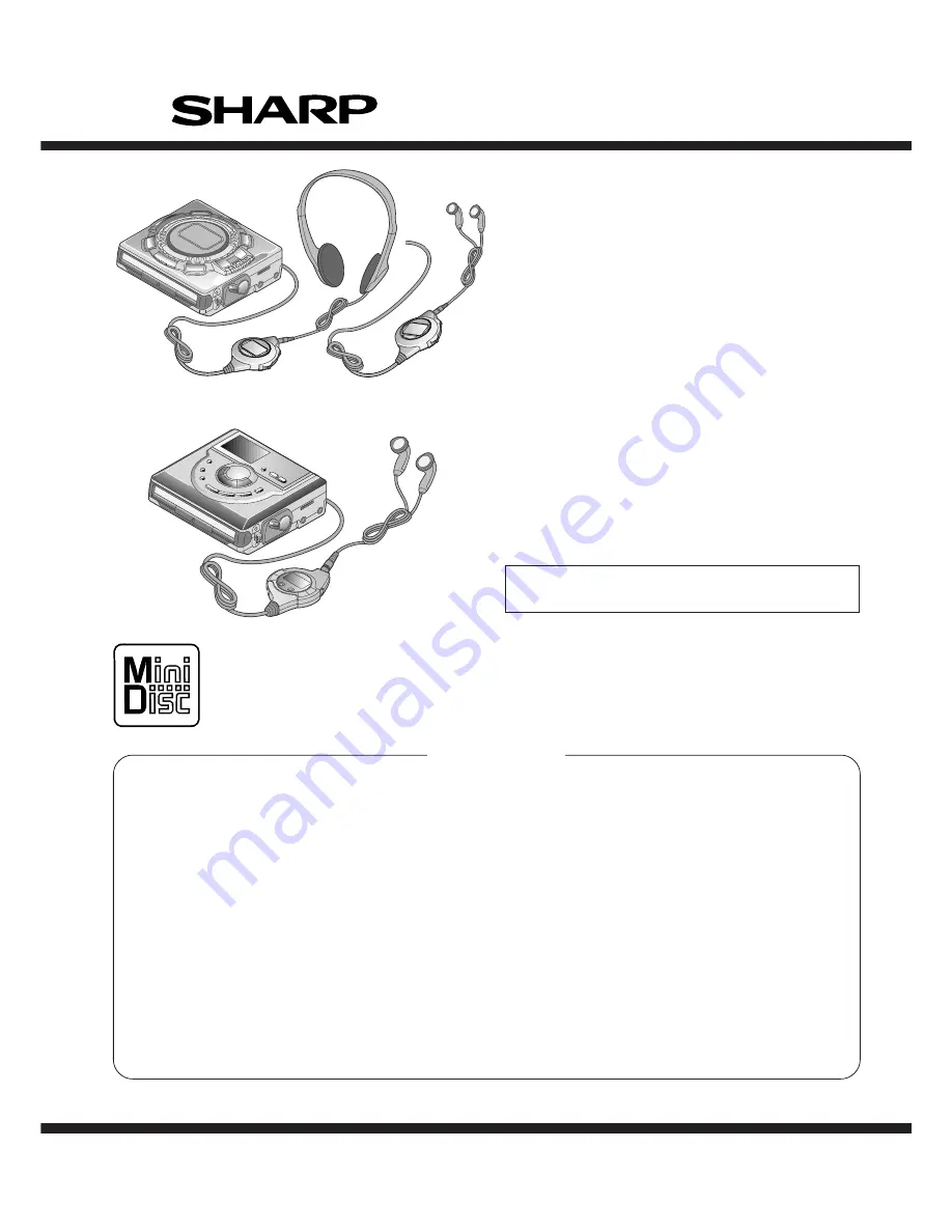
(Illustration: MD-MS721W)

(Illustration: MD-MS722/MS722C/MS722W)

Содержание MD-MS721BL

Страница 1: ... DIAGRAM 39 WAVEFORMS OF MD CIRCUIT 40 TROUBLE SHOOTING 41 FUNCTION TABLE OF IC 44 PARTS GUIDE EXPLODED VIEW PACKING OF THE SET MD MS722 ONLY MD MS722 MD MS722C MD MS722W MD MS721W BL MD MS721W S SERVICE MANUAL SHARP CORPORATION No SX891MDMS722U This document has been published to be used for after sales service only The contents are subject to change without notice In the interests of user safety...

Страница 2: ... not look into the Pickup Lens 2 The Laser Power Output of the Pickup inside the unit and replacement service parts have already been adjusted prior to shipping 3 No adjustment to the Laser Power should be attempted when replacing or servicing the Pickup 4 Under no circumstances look directly into the Pickup Lens at any time 5 CAUTION Use of controls or adjustments or performance of procedures oth...

Страница 3: ...rgeable battery Input socket Line optical digital microphone powered by the main unit Output socket Headphones impedance 19 ohms MS722 MS722C remote control unit Output socket Earphones impedance 32 ohms MS722W MS721W remote control unit MiniDisc Recorder Type Portable MiniDisc recorder Signal readout Non contact 3 beam semi coductor laser pick up Audio channels Stereo 2 channels monaural long pla...

Страница 4: ...ing Time Indicator 16 Total Track Number Display 17 Jog Dial 18 Record Track Mark Button 19 Volume Name Select Buttons 20 Display Lowercase Characters Button 21 Character Button 22 Volume Name Select Buttons 23 Play Pause Button 24 Fast Reverse Fast Forward Recording Level Control Cursor Shuttle Switch 25 Edit Auto Mark Time Mark Button 26 Mode Insert Button 27 Bass Delete Button 28 Enter Fast Pla...

Страница 5: ...isc Name Indicator 13 Track Name Indicator 14 Remaining Recording Time Indicator 15 Total Track Number Display 16 Mode Insert Button 17 Record Track Mark Button 18 Fast Reverse Recording Level Control Cursor Button 19 Play Pause Button 20 Fast Forward Recording Level Control Cursor Button 21 Display Lowercase Characters Button 22 Volume Name Select Buttons 23 Volume Name Select Buttons 24 Bass Del...

Страница 6: ...the battery is completely dis charged the whole battery indicator will flash Recharge the battery or replace the alkaline battery with a new one When the battery has run completely out BATT EMPTY main unit and Lo BATT remote control unit will appear Then the power will be disconnected automatically Notes When using the unit with an alkaline bat tery or a rechargeable battery the battery indicator ...

Страница 7: ...idental erasure Is the unit connected properly to the other equipment Is the AC adaptor unplugged or did a power failure occur whilst recording or editing Is the unit in the hold mode Is an optical signal being output from the external equipment Read the operation manual for the external equipment Even if the maximum recording time of a MiniDisc has not been reached DISC FULL or TOC FULL may be di...

Страница 8: ...emove the MiniDisc NO DISC A disc has not been loaded Load a disc PB DISC PROTECTED The disc is write protected You tried to record on a playback only disc Move the write protection knob back to its original position Replace it with a recordable disc POWER Improper power is being supplied Use one of the specified power sources SORRY SORRY Since a track number is currently being located or written ...

Страница 9: ...ina instalada OPEN O P E N O P E N OPEN O P E N O P E N OPEN DC IN 5V AC 120V 60Hz 120V CA 60Hz 1 4 3 2 RELEASE LOCK Back of the MD recorder Parte posterior de la grabadora de MD Open Abrir Press Pulsar 3 1 2 DC IN 5V AC 120V 60Hz 120V CA 60Hz Rechargeable battery power Alimentación de la batería recargable 2 1 Connection Conexión 3 Digital recording Grabación digital Analog recording Grabación an...

Страница 10: ...utton while in the stop mode Pulse el botón OFF estando en el modo de parada Playback does not start when a MiniDisc is inserted La reproducción no empieza cuando se inserta un minidisco Press the button In the following cases the auto play function will not work When the recordable MiniDisc write protection tab is closed When the auto play function has been canceled Pulse el botón En los casos si...

Страница 11: ...A2 x2 ø1 4x2mm B1 x1 ø1 4x2mm B1 x2 ø1 4x2mm Bottom Cabinet Top Cabinet Center Cabinet A1 x1 Pull C1 x1 ø1 7x2 5mm C1 x1 ø1 7x2 5mm B2 x1 C3 x3 B2 x1 Top Cabinet Pull Pull Pull Pull Pull Pull C2 x1 Flexble PWB for optical pickup C2 x1 C3 x1 Main PWB Put the fold on the connector and apply with the felt Sagging may result in contact with the sheet metal Felt Mechanism Unit ø1 4x2 5mm Figure 11 3 Ca...

Страница 12: ...t motor See Fig 12 2 1 Remove the solder joint B1 x 2 of slide motor lead wire 2 Remove the screw B2 x 1 pc and remove the flexible PWB 3 Remove the screw B3 x 1 pc and remove the lift motor Note Take care so that the motor gear is not damaged If the gear is damaged noise is caused How to remove the sled motor See Fig 12 3 1 Remove the stop washer C1 x 1 pc and remove the drive gear C2 x 1 pc 2 Re...

Страница 13: ...e perform manfully the preliminary adjustment Error rate indication jump test Continuous playback is performed error rate display jump test 5 RESULT 1 Mode The value adjusted in AUTO1 or MANUAL1 is indicated Execution in servo OFF state 6 RESULT 2 Mode The value adjusted in AUTO 2 or MANUAL 2 is indicated Adjustment value is changed manually error rate display jump test 7 TEST PLAY Mode Continuous...

Страница 14: ...he VOL UP button is pressed during setting indication the setting increases If the VOL DOWN button is pressed the setting reduces And then the new setting is stored in the RAM When the VOL UP DOWN button is held down the setting changes continuously one cycle being 100 ms If the STOP button is pressed during RESULT1 menu or measurement value indication or set value indication the state is changed ...

Страница 15: ...abled if the premastered disc or disc is in miserase protected state 9 NORMAL Mode When the STOP button is pressed while the NORMAl menu appears the mode changes to the TEST mode stop state Indication during operation Indication of memory capacity on main unit LCD Level meter Internal mode Address Cluster section Address Sector section Selection of sound volume BASS etc is possible without indicat...

Страница 16: ...n standby state 2 Start the EEPROM mode Temp menu Key operation in order of BASS SKIP DOWN x 2 times PLAY PLAY in the test mode STOP state TM is displayed Temperature code Temperature reference 3 Once press SKIP UP and determine the displayed microcomputer TEMP input AD value TPin is displayed TEMP input AD value 4 At the ambient temperature determine the temperature corrected value from the tempe...

Страница 17: ...H C T 1 _ 9 5 H C T 2 _ 4 0 H C T 3 _ 3 0 H R C 0 _ C 0 H R C 1 _ F E H S Y C _ A 6 H P W C _ 1 2 H P W L _ 6 6 H D R 1 _ 4 9 H D R 2 _ 4 9 H I N 1 _ D 4 H I N 2 _ 7 1 H I N H _ 6 4 H D R H _ 7 4 H P L E _ 9 6 H R C E _ 5 4 H E L T _ 7 2 H S L T _ 7 3 H S P M _ 0 0 H M S L _ 0 0 H U S 0 _ 0 0 H U S 1 _ 0 0 H U S 2 _ 0 0 H Item display Set values F G _ _ 6 3 H F F 1 _ 7 0 H F F 2 _ E 8 H F Z H _ E ...

Страница 18: ...M A N U 1 ATT manual adjustment menu M A N U 2 Error history display menu E D A T A Test mode normal playback menu N O R M A L Preautomatic Adjustment menu Preadjustment error adjustment value output During preadjustment adjustment Adjustment error Normal end Preadjustment normal end adjustment value output During ATT automatic adjustment PLAY PLAY A U T O 1 Preautomatic Adjustment A D J O K A D J...

Страница 19: ...tentative measurement Measurement value E signal offset EINO tentative measurement Measurement value F signal offset FINO tentative measurement Measurement value Laser On Play Power RF side focus gain coarse adjustment Gain setting A ATT focus tentative setting ATT setting B ATT focus tentative setting ATT setting RF side pit section tracking gain adjustment Gain setting Pit section adjustment COU...

Страница 20: ...P SKIP DOWN E H SKIP UP SKIP DOWN F H SKIP UP SKIP DOWN T H SKIP UP SKIP DOWN A L SKIP UP SKIP DOWN B L SKIP UP SKIP DOWN E L SKIP UP SKIP DOWN F L SKIP UP SKIP DOWN Temperature code displayATT manual adjustment menu Temperature code display Temperature code Laser ON Play Power Pit section E ATT tracking setting ATT setting Pit section E ATT tracking setting ATT setting High reflection A ATT focus...

Страница 21: ... H SKIP UP SKIP DOWN A L SKIP UP SKIP DOWN B L SKIP UP SKIP DOWN E L SKIP UP SKIP DOWN F L SKIP UP SKIP DOWN T H SKIP UP SKIP DOWN P T G SKIP UP SKIP DOWN G T G SKIP UP SKIP DOWN R C G SKIP UP SKIP DOWN R F G SKIP UP SKIP DOWN P C H SKIP UP SKIP DOWN G C H SKIP UP SKIP DOWN S A SKIP UP SKIP DOWN Continued to the next page SKIP UP SKIP DOWN B ATT focus initial setting E ATT tracking initial setting...

Страница 22: ...ed in the continued playback mode jump of specified number of lines occurs in the external periphery direction If the key is held down jump occurs continuously 100 ms cycle When the SKIP DOWN key is pressed in the continuous playback mode jump of specified number of lines occurs in the internal periphery direction If the key is held down jump occurs continuously 100 ms cycle Continuous record menu...

Страница 23: ...2 When the STOP key is pressed in specific menu the TEST MODE STOP state is set Error history display menu Error history 0 display Error code Error history 1 display Error code Error history 2 display Error code Error history 3 display Error code Error history 4 display Error code Error history 5 display Error code Error history 6 display Error code Error history 7 display Error code Error history...

Страница 24: ...P UP SKIP DOWN B S 3 SKIP UP SKIP DOWN When the STOP key is pressed in specific menu the TEST MODE STOP state is set When the DISP key operation is performed in the specific state the menu changes to TEMP SETTING menu In the specific state the setting changes in the range of 00h to FFh when the VOL UP DOWN key is pressed The upper limit varies depending on the items Focus setting menu PLAY F o c u...

Страница 25: ...depending on the items S C o SKIP UP SKIP DOWN S C t SKIP UP SKIP DOWN S C m SKIP UP SKIP DOWN C L p SKIP UP SKIP DOWN C L v SKIP UP SKIP DOWN J P i SKIP UP SKIP DOWN K 1 0 SKIP UP SKIP DOWN Spin setting menu PLAY S p i n Spin Setting S P G S P i SKIP UP SKIP DOWN S P m SKIP UP SKIP DOWN S P o SKIP UP SKIP DOWN S P 1 SKIP UP SKIP DOWN S P 2 SKIP UP SKIP DOWN S P 3 SKIP UP SKIP DOWN S P 4 SKIP UP S...

Страница 26: ...lue PLAY T e m p TEMP Setting T M T p i n SKIP UP SKIP DOWN When the STOP key is pressed in specific menu the TEST MODE STOP state is set When the DISP key operation is performed in the specific state the menu changes to TEMP SETTING menu In the specific state the setting changes in the range of 00h to FFh when the VOL UP DOWN key is pressed Adjustment setting menu PLAY A D J S E T Adjustment Sett...

Страница 27: ...c state the menu changes to TEMP SETTING menu In the specific setting display state the setting change digit changes when the P MODE key is pressed 1st digit initial value 2nd digit P MODE P MODE In the specific state the setting changes in the range of 0h to Fh when the VOL UP DOWN key is pressed Control setting menu PLAY C T R L Control Setting C T 0 C T 1 SKIP UP SKIP DOWN C T 2 SKIP UP SKIP DO...

Страница 28: ...OWN SKIP UP SKIP DOWN U S 1 U S 2 When the STOP key is pressed in specific menu the TEST MODE STOP state is set When the DISP key operation is performed in the specific state the menu changes to TEMP SETTING menu In the specific setting display state the setting change digit changes when the P MODE key is pressed 1st digit initial value 2nd digit P MODE P MODE In the specific state the setting cha...

Страница 29: ...3 REMOTE CONTORL J801 DC IN 4 5 5V 2 9 4 1V 3 4V VCC VCC 2 35 DISPLAY UNIT OPERATION UNIT IC901 3 PHASE BRUSHLESS DRIVER BA6965AF IC703 AUDIO AMP IR3R54N IC701 AUDIO AMP IR3R54N IC601 PWM DRIVER 17A39TD VM VCC IC402 EEPROM S29L294A 4 5 VCC VS IC202 16BIT D RAM IX2723AF 2 5 2 5 4 5 OPTICAL IN UNIT J701 DIGITAL INPUT J701 LINE INPUT J702 MIC IN READY FOR PLUG IN POWER J703 HEADPHONES LINE 1 6 19 20 ...

Страница 30: ...99 100 8 7 6 5 4 3 2 1 10 11 12 13 14 15 16 17 18 19 20 21 22 23 24 25 26 26 27 27 28 28 29 30 31 32 33 34 35 36 37 38 39 40 41 42 43 44 45 46 47 48 48 49 49 50 50 51 525354 5556 57 58 59 60 61 6263 64 6566 6 9 8 7 6 5 4 3 2 1 CN101 22 21 20 19 18 17 16 15 14 13 12 11 10 22 21 20 19 18 17 16 15 14 13 12 11 10 9 8 7 6 5 4 3 2 1 1615 14 1312 1110 9 8 7 6 5 4 3 2 1 CN601 M903 LIFT MOTOR PH901 GP1S93K...

Страница 31: ...9 40 41 42 43 44 45 46 47 48 48 49 49 50 50 51 525354 5556 57 58 59 60 61 6263 64 6566 67 6869 70 71 72 73 74 75 76 77 78 79 80 81 82 83 84 85 86 87 88 89 90 91 92 93 94 95 96 97 98 98 99 99 100 100 8 7 6 5 4 3 2 1 4 1 R481 36K R482 18K IC771 TK71225M 5 4 3 2 1 C605 0 1 TP610 C600 22 6 3 L600 2 2 C773 0 22 C774 1 C 0 C507 10 6 3 R500 4 7 C506 0 001 C505 0 001 R P RESET RKEY HDON PCNT1 PHOLD SYD7 S...

Страница 32: ...510 2 2 C509 2 2 R502 470 R501 470 C502 0 0022 C501 0 0022 C504 3 3 10 C503 3 3 10 TP500 L500 22µH C508 1 C500 10 6 3 IC501 AK4519VF AD DA CONVERTER C722 3 3 10 C760 0 027 TP704 TP702 TP707 R715 100K R716 100K C734 0 1 16 C733 0 1 16 C754 1 R729 2 7K R730 2 7K C759 0 027 TP807 L851 4 7µH IC851 CPH3403 C856 1 16 C854 0 01 R857 100K D851 RB521S30 D852 F1J2F C857 10 CH L852 10µH C853 10P R853 330K R8...

Страница 33: ...0V 0V 0V 0V 0V 0V 0V 0V 1 2 3 4 5 6 7 8 9 10 IC651 VOLTAGE NO PIN 0V 0 24V 0V 0V 0 73V 0 73V 1 2 3 4 5 6 IC801 VOLTAGE NO PIN 0V 0V 2 35V 0V 0V 2 35V 0V 0 91V 2 5V 0V 0 91V 2 35V 0V 4 54V 1 2 3 4 5 6 7 8 9 10 11 12 13 14 IC351 VOLTAGE NO PIN 1V 2 5V 1 27V 0V 1 27V 1 27V 1 27V 1 27V 126V 2 2V 1 43V 2V 0V 0V 0V 0V 1V 0V 0V 0V 0V 0V 0V 0V 0V 1 58V 0 87V 0 87V 1 73V 1 1V 2 5V 0 6V 0 8V 1 9V 0 9V 1 29V...

Страница 34: ...1 C171 C172 C202 L202 1 6 7 12 13 18 19 24 L201 C201 IC201 C212 R222 C211 C442 C203 R204 C204 IC601 L601 L602 L603 L604 C604 C622 1 5 10 15 18 19 20 25 30 35 36 L651 C651 C603 L600 C600 C602 C601 R455 R456 R457 R426 C605 IC651 R425 R452 R454 R451 R453 R458 C837 D836 L771 C826 C803 C505 C506 R207 L204 XL201 C774 IC771 C773 1 1 3 4 5 5 10 12 13 15 20 24 L500 C500 C508 C507 R500 J701 OPTICAL LINE IN ...

Страница 35: ...2 R412 CN601 R903 R401 1 11 10 15 20 5 R901 R902 C907 C906 C905 R904 R404 R411 C354 C910 C130 C106 C107 C110 R423 C109 R422 SW402 HOLD C854 R860 R813 R756 R757 C760 C813 R832 R848 R845 R846 R819 R762 R770 R761 1 5 10 12 13 15 20 24 R857 R826 C859 R855 R854 D431 C712 R769 R712 R711 IC841 CN482 IC703 C753 R763 D841 D842 C765 D843 R849 R909 P38 6 H P38 4 E G P38 6 C P38 1 C TP115 TP105 TP108 TP106 TP...

Страница 36: ...171 C171 C172 C202 L202 1 6 7 12 13 18 19 24 L201 C201 IC201 C212 R222 C211 C203 R204 C204 IC601 L601 L602 L603 L604 C604 C622 1 5 10 15 18 19 20 25 30 35 36 L651 C651 C603 L600 C600 C602 C601 R455 R456 R457 R426 C605 IC651 R425 R452 R454 R451 R453 R458 C837 D836 L771 C826 C803 C505 C506 R207 L204 XL201 C774 IC771 C773 1 1 3 4 5 5 10 12 13 15 20 24 L500 C500 C508 C507 R500 J701 OPTICAL LINE IN J70...

Страница 37: ...2 R412 CN601 R903 R401 1 11 10 15 20 5 R901 R902 C907 C906 C905 R904 R404 R411 C354 C910 C130 C106 C107 C110 R423 C109 R422 SW402 HOLD C854 R860 R813 R756 R757 C760 C813 R832 R848 R845 R846 R819 R762 R770 R761 1 5 10 12 13 15 20 24 R857 R826 C859 R855 R854 D431 C712 R769 R712 R711 IC841 CN482 IC703 C753 R763 D841 D842 C765 D843 R849 R909 P38 6 H P38 4 E G P38 6 C P38 1 C TP115 TP105 TP108 TP106 TP...

Страница 38: ...OTOR M901 SPINDLE MOTOR M903 LIFT MOTOR MECHANISM FLEXIBLE PWB UNIT 8 MAGNETIC HEAD FLEXIBLE PWB 23 MAGNETIC HEAD 32 KEY FLEXIBLE PWB ASS Y 248 KEY FLEXIBLE PWB ASS Y 248 CN101 TO MAIN PWB P33 11 H CN601 TO MAIN PWB P35 37 12 D CN451 TO MAIN PWB P35 37 12 D CN451 TO MAIN PWB P35 37 11 A LCD 249 CN482 MD MS722 C W MD MS721W PH901 SW901 SW902 ...

Страница 39: ...to electro lytic capacitor the expression capacitance withstand volt age is used CH TH RH UJ Temperature compensation ML Mylar type The indicated voltage in each section is the one measured by Digital Multimeter between such a section and the chas sis with no signal given Parts marked with are important for maintaining the safety of the set Be sure to replace these parts with specified ones for ma...

Страница 40: ...L CH1 0 000V CH2 0 00V Main 1K Zoom 1K CH3 0 00V CH4 0 00V Trigger Mode AUTO Type EDGE CH1 Detay 0 0ns Hold OFF MINIMUM T TP201 EFM Stopped CH1 2V DC 10 1 500ms div 500ms div 1 MORM 200MS s 9 1994 12 15 08 57 26 Filter Offset Record Length Smoothiing OFF BW FULL CH1 0 00V CH2 0 00V Main 10K Zoom 10K CH3 0 000V CH4 0 0V Trigger Mode NORMAL Type EDGE CH1 Detay 0 0ns Hold OFF MINIMUM T TP201 EFM TP21...

Страница 41: ...eaning tissue and a small amount of isopropyl alcohol Do not touch the lens with the bare hand Is the power supply turned on when the remote control button or main unit button is pressed No Perform the check stated in item Power is not turned on when the PLAY button is pressed Perform the check stated in item Abnormal display No Yes Does the display operate normally Is playback state set Yes Perfo...

Страница 42: ...ck time display advance Yes Position check in INNER mode Check IC201 and IC202 connection line Is the lead in photointerrupter set to OFF when the optical pickup moves to the innermost periphery in NORMAL mode Is TP660 in H level Check the lead in photointerrupter mechanical flex PWB soldering and CNS601 connection No Ia an attempt to repeat repeatedly the TOC part performed on the low reflection ...

Страница 43: ...Check whether disc is record inhibited No Does the RF waveform of TP201 appear when playback is Does level of pins 34 of IC401 and pin 17 of IC101 change depending on record and playback Is RF pattern output from IC201 pin 50 Yes No Check for soldering failure of IC201 No Check periphery of IC401 and IC101 Check whether there is any damage in IC101 periphery of laser diode Yes Check for defects of...

Страница 44: ...MCPGI Input Microphone plug insertion detection input 34 PC2 _INPGI Input Line digital plug insertion detection 35 PC3 INPGCK Input Line digital plug type detection 36 PC4 RCPCNT Output Record circuit power control output 37 PC5 TEST1 Input Test mode setting input 1 38 PC6 TEST0 Input Test mode setting input 0 39 PC7 JPNP Input Kana conversion Kana input existence nonexistence discrimination 40 Vc...

Страница 45: ...t 80 AN1 PLVDCI Input DC jack voltage detection input 81 AN2 PLVINN Input Lithium battery voltage detection input 82 AN3 RKEY Input Remote control key operation detection input 83 AN4 HKEY1 Input Unit key operation detection input 1 84 AN5 HKEY2 Input Unit key operation detection input 2 85 AN6 TEMP Input Ambient temperature detection input 86 DA1 LDVAR Output P U laser power setting output 87 AVs...

Страница 46: ...MD MS722 C WMS721W 46 M E M O ...

Страница 47: ...lindrical type without lead wire VC MN Cylindrical type without lead wire VC TV Square type without lead wire VC TQ Square type without lead wire VC CY Square type without lead wire VC CZ Square type without lead wire VC J The 13th character represents capacity difference J 5 K 10 M 20 N 30 C 0 25 pF D 0 5 pF Z 80 20 If there are no indications for the electrolytic capacitors error is 20 Resistors...

Страница 48: ... Impeder 150mA L453 454 RCILC0353AFZZ J AB Tip Solid Induction 100mA L456 458 RCILC0353AFZZ J AB Tip Solid Induction 100mA L491 VPBNN4R7M0000 J AC 4 7 µH L500 VPCBM220K0000 J AC 22 µH L600 RCILC0331AFZZ J AC 2 2 µH Choke L601 604 RCILC0358AFZZ J AC 4 7 µH Choke L608 RCILC0359AFZZ J AC 100 µH Choke L609 610 RCILC0358AFZZ J AC 4 7 µH Choke L651 VPBNNR47M0000 J AC 0 47 µH L702 703 RCILC0353AFZZ J AB ...

Страница 49: ...lytic Tantalume C902 VCKYCY1EB103K J AA 0 01 µF 25V C903 RC KZ1186AFZZ J AD 3 3 µF 10V Electrolytic C905 907 VCKYCY1HB222K J AA 0 0022 µF 50V C908 RC KZ1204AFZZ J AB 0 22 µF 10V Electrolytic C909 910 VCKYCY1CB333K J AA 0 033 µF 16V C911 VCKYCY1CB104K J AB 0 1 µF 16V RESISTORS VRS CY1JB000J J AA 0 ohm Jumper 0 8 1 55mm Green R101 104 VRS CY1JB223J J AA 22 kohms 1 16W R105 VRS CY1JB394J J AA 390 koh...

Страница 50: ...USG0599AFZZ J AB Cushion 8 QPWBH0326AFM1 J AM Mechanism Flexible PWB Ass y 8 1 Mechanism Flexible PWB Not Replacement Item 8 2 SW901 QSW M0169AFZZ J AD Switch Push Type Disc In 8 3 SW902 QSW M0170AFZZ J AD Switch Push Type Disc Protect 8 4 PH901 VHPGP1S93K 1 J AF Photo Interrupter GP1S93K 9 MSPRP0925AFFJ J AD Driver Screw Bracket 11 MSPRP0923AFFJ J AD Plate Spring 12 MSPRP0924AFM1 J AD Shutter Spr...

Страница 51: ... MS721W S MS721W BL 248 RUNTK0489AFZZ J AU Key Flexible PWB Ass y MS722 MS722C MS722W 248 RUNTK0493AFZZ J AQ Key Flexible PWB Ass y MS721W S MS721W BL 249 RUNTZ0704AFZZ J AY LCD MS722 MS722C MS722W 249 RUNTZ0705AFZZ J AY LCD MS721W S MS721W BL 251 PSHEZ0994AFZZ J AB Sheet Switch B MS722 MS722C MS722W Only 252 PGUMS0730AFZZ J AB Cushion Mechanism B MS722 MS722C MS722W Only 253 HDECQ0584AFSA J AQ Al...

Страница 52: ... Taiwan TINSE1642AFZZ J Operation Manual MS721W S MS721W BL for Australia New Zealand TINSE1643AFZZ J AG Operation Manual MS722W for Australia New Zealand TINSK0369AFZZ J Operation Manual MS722C TINSZ1381AFZZ J AG Operation Manual MS722 TINSZ1382AFZZ J AD Quick Guide MS722 Only TINSZ1383AFZZ J AN Operation Manual MS722W Except for Australia New Zealand TINSZ1386AFZZ J AN Operation Manual MS721W S ...

Страница 53: ...G H 1 2 3 4 5 6 Figure 6 MD MECHANISM EXPLODED VIEW 6 1 2 7 509 3 12 6 5 20 4 23 30 518x2 514 514 506 8 503 11 13 504 29 15 18 16 505 M903 M902 M901 28 503x2 502x3 32 511x2 508 508 8 4 PH901 8 1 8 2 SW901 8 3 SW902 9 25 515 27 516 517 ...

Страница 54: ...9 216 201 2 602 201 5 603 201 1 201 601 201 4 201 3 220 256 208 207 601 210 209 205 206 607 606x2 202 1 223x2 202 2 202 225x2 222 234 225x2 606 601 604 228x2 604 204 4 204 1 204 2 204 3 606 606x2 606x2 602 605 204 218 218 266 265 261 231 232 233 246 252 221 MS722 C W MS721W S MS721W BL 253 249 254 239 238 241 237 248 264x3 202 260x2 202 1 202 2 259 255 246 262 263 MD MECHANISM Except for MS722 ...

Страница 55: ...d RCA Type AC Adaptor Headphones Remote Control Packing Add SPAKA2704AFZZ Packing Case SPAKC6672AFZZ Pad AC Adaptor SPAKZ0489AFZZ Rechargeable Battery Strap Connecting Cord Optical Type Operation Manual Carrying Case UBAGC0076AFSA Quick Guide Packing Add Unit SPAKZ0498AFZZ Packing Add Unit SPAKZ0509AFZZ Caution Headphones Not Replacement Item Paper Bag Unit SSAKP0116AFZZ ...

Страница 56: ...rieval system or transmitted in any from or by any means electronic mechanical photocopying recording or otherwise without prior written permission of the publisher A9812 3516NS HA M SHARP CORPORATION Communication Systems Group Quality Reliability Control Center Higashihiroshima Hiroshima 739 0192 Japan Printed in Japan SC SL EX SA SZ ...

Отзывы: