CD-SW440N
CD
USB
TAPE
AUDIOIN
PHONES
POWER
ON/STAND-BY
FUNCTION
MINI COMPON
ENT SYSTEM
CD-SW440
PUSH
OPEN
SERVICE MANUAL
No. SX948CDSW440N
This document has been published to be used
for after sales service only.
The contents are subject to change without notice.
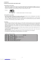
PRECAUTIONS FOR USING LEAD-FREE SOLDER
CHAPTER 1. GENERAL DESCRIPTION
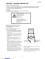
[1] Important Service Safety Precaution ............. 1-1
[2] Important Service Notes (for U.S.A only)....... 1-1
[3] Specifications ................................................ 1-2
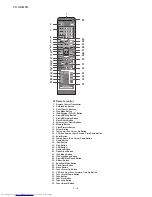
[4] Name Of Parts............................................... 1-3
CHAPTER 2. ADJUSTMENTS
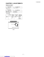
[1] Mechanism
Section ....................................... 2-1
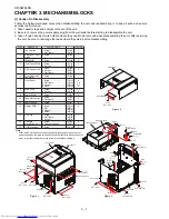
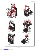
CHAPTER 3. MECHANISM BLOCKS
[1] Caution On Disassembly ............................... 3-1
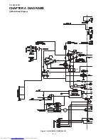
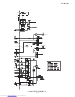
CHAPTER 4. DIAGRAMS
[1] Main
Block
Diagram ...................................... 4-1
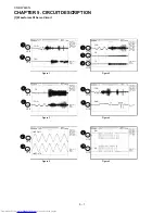
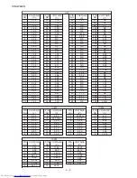
CHAPTER 5. CIRCUIT DESCRIPTION
[1] Waveforms Of Servo Circuit .......................... 5-1
[2] Voltage........................................................... 5-2
CHAPTER 6. CIRCUIT SCHEMATICS AND PARTS
LAYOUT
[1] Notes On Schematic Diagram ....................... 6-1
[2] Types Of Transistor And LED ....................... 6-1
[3] Schematic
Diagram........................................ 6-2
[4] Charts Of Connecting Wires ...................... 6-22
[5] Wiring Side Of PWB..................................... 6-24
CHAPTER 7. FLOWCHART
[1] Troubleshooting ............................................. 7-1
CHAPTER 8. OTHERS
[1] Function Table Of IC ...................................... 8-1
[2] FL
Display ...................................................... 8-9
PARTS GUIDE
MINI COMPONENT SYSTEM
CD-SW440N
MODEL
CD-SW440N Mini Component System consisting of
CD-SW440N (main unit), CP-S440N (speaker system) and
CP-SW440N (subwoofer).
CONTENTS
SHARP CORPORATION
Parts marked with "
" are important for maintaining the safety of the set. Be sure to replace these parts with
specified ones for maintaining the safety and performance of the set.
!
• In the interests of user-safety the set should be restored
to its original condition and only parts identical to those
specified be used.
iPod is a trademark of Apple Inc.,
registered in the U.S. and other countries.
“Made for iPod” means that an electronic accessory has
been designed to connect specifically to iPod and has been
certified by the developer to meet Apple performance
standards.
Apple is not responsible for the operation of this device or its
compliance with safety and regulatory standards.
Содержание CD-SW440N
Страница 19: ...CD SW440N 6 3 Figure 6 2 MAIN SCHEMATIC DIAGRAM 2 6 7 8 9 10 11 12 ...
Страница 20: ...CD SW440N 6 4 Figure 6 3 MAIN SCHEMATIC DIAGRAM 3 6 FAN MOTOR TO SPEAKER SYSTEM 13 14 15 16 17 18 ...
Страница 21: ...CD SW440N 6 5 Figure 6 4 MAIN SCHEMATIC DIAGRAM 4 6 USB IN TO SERVO PWB A B C D E F G H 1 2 3 4 5 6 ...
Страница 22: ...CD SW440N 6 6 Figure 6 5 MAIN SCHEMATIC DIAGRAM 5 6 TO SERVO PWB 7 8 9 10 11 12 ...
Страница 23: ...CD SW440N 6 7 Figure 6 6 MAIN SCHEMATIC DIAGRAM 6 6 L CH R CH 13 14 15 16 17 18 ...
Страница 24: ...CD SW440N 6 8 Figure 6 7 POWER SCHEMATIC DIAGRAM 1 2 POWER PWB B1 25V A B C D E F G H 1 2 3 4 5 6 ...
Страница 25: ...CD SW440N 6 9 Figure 6 8 POWER SCHEMATIC DIAGRAM 2 2 AC POWER SUPPLY CORD AC 120V 60Hz 7 8 9 10 11 12 ...
Страница 27: ...CD SW440N 6 11 Figure 6 10 DISPLAY TAPE SCHEMATIC DIAGRAM 2 2 7 8 9 10 11 12 ...
Страница 29: ...CD SW440N 6 13 Figure 6 12 DISPLAY TAPE SCHEMATIC DIAGRAM 2 2 7 8 9 10 11 12 ...
Страница 36: ...CD SW440N 6 20 Figure 6 19 iPod SCHEMATIC DIAGRAM 1 2 iPod PWB D iPod SIGNAL 367 A B C D E F G H 1 2 3 4 5 6 ...
Страница 37: ...CD SW440N 6 21 Figure 6 20 iPod SCHEMATIC DIAGRAM 2 2 7 8 9 10 11 12 ...
Страница 43: ...CD SW440N 6 27 Figure 6 26 WIRING SIDE OF MAIN PWB BOTTOM VIEW 2 2 JP24 7 8 9 10 11 12 ...
Страница 45: ...CD SW440N 6 29 MEMO ...
Страница 49: ...CD SW440N 6 33 Figure 6 31 WIRING SIDE OF DISPLAY TAPE PWB BOTTOM VIEW 2 2 7 8 9 10 11 12 ...


