7
LC-37HV4E
Preparation
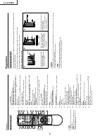
Where to place the System
“System
” means the Display and A
VC System. First select the location wher
e to place the System.
1
2
Selecting the location of the System
•
Select a place with no dir
ect sunlight and good ventilation.
•
The Display and the A
VC System ar
e connected by the system cable.
Setting the System in place
Handling the Displa
y
CA
UTION
•
The Display is ver
y heavy
. Move it with two or mor
e people.
•
Do not r
emove the stand fr
om the Display unless using an
optional bracket to mount it.
•
When moving, put your hands on the Display
, but never on the
Display speakers.
•
Keep enough space above and behind the Display
.
Handling the A
VC System
CA
UTION
•
Do not put a VCR or other device on the A
VC System.
•
Keep enough space above and on the sides of the A
VC System.
•
Do not block the ventilation openings on the top and left side,
and the exhaust fan on the right side.
•
Do not spr
ead a thick cloth beneath the A
VC System, or cover it
with one, as this can cause overheating and r
esult in malfunction.
System cable
Displa
y
A
VC System
If you want to keep a longer distance between the
Display and A
VC System, please pur
chase the
optional system cable AN-07SC1 (about 7 meters).
CA
UTION
Adjust the screen with both
hands. Put one hand on the
Display and tilt the screen
while steadying the stand
with your other hand.
You can adjust the screen
vertically up to 4 degrees
forward or 6 degrees back-
ward, or rotate 10 degrees
horizontally.
5 cm or mor
e
5 cm or mor
e
on both sides
Keep enough space
Ther
e is an exhaust fan
on the right side.
10 cm
or mor
e
AC INPUT
110V
–
240V
DISPLAY INPUT1
DISPLAY INPUT2
System cable
A
VC System (rear vie
w
)
AC cor
d
Displa
y
(rear vie
w
)
AC cor
d
System cable
(GREY)
Connect the plug fir
mly
until the hooks on both
sides click.
(WHITE)
Connect the plug into
the ter
minal and secur
e
it by tightening the
thumb scr
ews.
(GREY)
(WHITE)
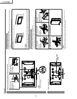
Setting the System
After putting the Display and the A
VC System in place, connect the system cables and AC cor
ds. Use the
cable clamps for bundling the cables.
Press do
wn the tw
o
upper hooks to remo
ve
the co
ver to
war
d y
ou.
Connecting the system cab
le and the A
C
cor
d to the Displa
y
1
2
3
Remo
ving the terminal co
ver
Connecting the system cab
le and the A
C
cor
d to the A
VC System
CA
UTION
•
T
O
PREVENT RISK OF ELECTRIC SHOCK,
DO NO
T
T
OUCH UN-INSULA
TED P
A
R
TS OF ANY CABLES
WITH
THE
A
C
CORD CONNECTED
.
Press the tw
o hooks
to
war
d the centre of the
Displa
y
and remo
ve the
co
ver to
war
d y
ou.
Содержание AQUOS LC-37HV4E
Страница 26: ...26 LC 37HV4E 8 7 10 9 6 5 4 3 2 1 A B C D E F G H CHASSIS LAYOUT ...
Страница 27: ...27 LC 37HV4E 17 16 19 18 15 14 13 12 11 10 ...
Страница 33: ...LC 37HV4E 33 6 5 4 3 2 1 A B C D E F G H Ë Ë Ë Ë Ë R C LED Unit Display ...
Страница 34: ...34 LC 37HV4E 8 7 10 9 6 5 4 3 2 1 A B C D E F G H Ë MAIN Unit 1 9 Display ...
Страница 35: ...35 LC 37HV4E 17 16 19 18 15 14 13 12 11 10 ...
Страница 36: ...36 LC 37HV4E 8 7 10 9 6 5 4 3 2 1 A B C D E F G H Ë MAIN Unit 2 9 Display ...
Страница 37: ...37 LC 37HV4E 17 16 19 18 15 14 13 12 11 10 ...
Страница 38: ...38 LC 37HV4E 8 7 10 9 6 5 4 3 2 1 A B C D E F G H Ë MAIN Unit 3 9 Display ...
Страница 39: ...39 LC 37HV4E 17 16 19 18 15 14 13 12 11 10 ...
Страница 40: ...40 LC 37HV4E 8 7 10 9 6 5 4 3 2 1 A B C D E F G H Ë MAIN Unit 4 9 Display ...
Страница 41: ...41 LC 37HV4E 17 16 19 18 15 14 13 12 11 10 ...
Страница 42: ...42 LC 37HV4E 8 7 10 9 6 5 4 3 2 1 A B C D E F G H Ë MAIN Unit 5 9 Display ...
Страница 43: ...43 LC 37HV4E 17 16 19 18 15 14 13 12 11 10 ...
Страница 44: ...44 LC 37HV4E 8 7 10 9 6 5 4 3 2 1 A B C D E F G H Ë MAIN Unit 6 9 Display ...
Страница 45: ...45 LC 37HV4E 17 16 19 18 15 14 13 12 11 10 ...
Страница 46: ...46 LC 37HV4E 8 7 10 9 6 5 4 3 2 1 A B C D E F G H Ë MAIN Unit 7 9 Display ...
Страница 47: ...47 LC 37HV4E 17 16 19 18 15 14 13 12 11 10 ...
Страница 48: ...48 LC 37HV4E 8 7 10 9 6 5 4 3 2 1 A B C D E F G H Ë MAIN Unit 8 9 Display ...
Страница 49: ...49 LC 37HV4E 17 16 19 18 15 14 13 12 11 10 ...
Страница 50: ...50 LC 37HV4E 8 7 10 9 6 5 4 3 2 1 A B C D E F G H Ë MAIN Unit 9 9 Display ...
Страница 51: ...51 LC 37HV4E 17 16 19 18 15 14 13 12 11 10 ...
Страница 52: ...52 LC 37HV4E 8 7 10 9 6 5 4 3 2 1 A B C D E F G H Ë Ë Ë Ë Ë AUDIO Unit 1 2 Display ...
Страница 53: ...53 LC 37HV4E 17 16 19 18 15 14 13 12 11 10 ...
Страница 54: ...54 LC 37HV4E 8 7 10 9 6 5 4 3 2 1 A B C D E F G H Ë Ë Ë Ë Ë AUDIO Unit 2 2 Display ...
Страница 55: ...55 LC 37HV4E 17 16 19 18 15 14 13 12 11 10 ...
Страница 56: ...6 5 4 3 2 1 A B C D E F G H LC 37HV4E 56 Ë Ë Ë Ë Ë INVERTER 1 Unit Display ...
Страница 57: ...LC 37HV4E 57 6 5 4 3 2 1 A B C D E F G H Ë INVERTER 2 Unit Display ...
Страница 58: ...6 5 4 3 2 1 A B C D E F G H LC 37HV4E 58 Ë Ë Ë Ë Ë INVERTER 3 Unit Display ...
Страница 59: ...LC 37HV4E 59 6 5 4 3 2 1 A B C D E F G H Ë INVERTER 4 Unit Display ...
Страница 60: ...60 LC 37HV4E 8 7 10 9 6 5 4 3 2 1 A B C D E F G H Ë Ë Ë Ë Ë Power Unit Display ...
Страница 61: ...61 LC 37HV4E 17 16 19 18 15 14 13 12 11 10 ...
Страница 62: ...6 5 4 3 2 1 A B C D E F G H LC 37HV4E 62 Ë KEY Unit Display ...
Страница 63: ...LC 37HV4E 63 6 5 4 3 2 1 A B C D E F G H Ë Ë Ë Ë Ë SPEAKER R Unit Display Ë SPEAKER L Unit Display ...
Страница 65: ...65 LC 37HV4E 17 16 19 18 15 14 13 12 11 10 ...
Страница 68: ...68 LC 37HV4E 8 7 10 9 6 5 4 3 2 1 A B C D E F G H MAIN Unit Side B Ë Ë Ë Ë Ë Display ...
Страница 69: ...69 LC 37HV4E 17 16 19 18 15 14 13 12 11 10 ...
Страница 72: ...72 LC 37HV4E 8 7 10 9 6 5 4 3 2 1 A B C D E F G H AUDIO Unit Component Side Ë Ë Ë Ë Ë Display ...
Страница 73: ...73 LC 37HV4E 17 16 19 18 15 14 13 12 11 10 ...
Страница 84: ...6 5 4 3 2 1 A B C D E F G H LC 37HV4E 84 Ë Ë Ë Ë Ë Display POWER Unit Component Side ...
Страница 85: ...LC 37HV4E 85 6 5 4 3 2 1 A B C D E F G H Ë Ë Ë Ë Ë Display POWER Unit Wiring Side ...


