background image

13

29H-FG3RU

13-1

13-2

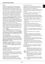
PIF ADJUSTMENT

No.

Adjustment point

Adjustment condition/procedur

eW

aveform or remarks

RF-AGC

T

AKE OVER

POINT AD-

JUSTMENT

(I

2

C BUS

CONTROL)

1

1.

Receive "P

AL

 COLOR BAR" signal

.

Signal Strength: 54 

±

 1dB

µ

V  

(75 

ohm 

termination)

2.

Connect the oscilloscope to 

TP53 (T

uner's 

AGC

Te

rminal) as shown in figure 3-1.

3.

Select "RF-AGC" item in the 

Adjustment Mode.

Adjust the "RF-AGC" bus data to obtain the 

T

uner

output pin drop 0.1V 

~


1.0V below maximum volt-

age.

4.

Change the antenna input signal to 63 ~ 67dB

µ

V,

and make sure there is no noise.

5.

Set the RF 

AGC to 0 - 6 V with no saturation with

the waveform.

6.

T

urn up the input signal to 90 ~ 95 dB

µ

V to 

be 

sure

that there is no cross modulation beat

.

Fig. 3

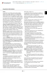
PURITY

 ADJUSTMENT

No.

Adjustment point

Adjustment conditions/procedure

W

aveform or remarks

PURITY

 ADJ.

1.

Select the green monocolor screen with remote

contoller

, and set the beam current of 1.7mA

with the contrast control.

2.

Degauss the CR

T

 enough with the degausing coil.

 Note:  


Follow the 

job 

instruction 

manual 

to 

adjust the magnetic field.

.

3.

The purity magnet must be previously set at the

0 magnetic field, and the convergence must be

adjusted  to be rough.

With P-MAG, adjust it to the center - rank 

A.

4.

Observe the points a,b, as shown in Fig.1-1

through the microscope.

 Move DY fore and aft to set the landing at the

point (Rank 

A).

5.

If the a/b balance is poor

, compensate it to the

center "Rank 

AB".

6.

Aline it to zero, keeping the raster rotation in th

e

east direction.

6.

T

ighten the deflection coil fastening screws.

»

 Ti

ghtening torque : 108N 

±

 20N (1

1Kgf 

±

 2Kgf)

8.

Checking the CR

T

 corner area, bond the mag-

netic sheet to set the landing at rank 

A

 for com-

pensation.

Note:

Apply the adjustment after aging with

the beam current 1700 

±

 50

µ

A or more

for 30 minutes or more.

Note:

Select the service mode, and press th

e

monocolor key of R/C for process, and

the monocolor screen (green) will be

selected.

1

a

b

A

B

A

90mm

90mm

B

A = B

A = B

Fig.1-1

Fig. 1-2

Rank "A"

(on the right of the CR

T)

Fig. 1-3

Rank "A"

(on the left of the CR

T)

*

Continuosly press the mono-

colour key 1 second or more,

and the monocolour mode will

be selected without the service

mode.

*Even with 

TEXT

 key or "R/G/B"

key

, it can be directly switched to

each monocolor screen.

Monocolour

screen release

Monocolour

GREEN

screen

Monocolour

BLUE

screen

Monocolour

RED

screen

*A

djustment for uniformity is change to another

content. Please refer to the following page.

*E

very push of the monocolour key changes the

screen as follows.

Содержание 29H-FG3RU

Страница 1: ...IC DIAGRAM 28 SCHEMATIC DIAGRAM CRT UNIT 29 MAIN UNIT 30 FRONT UNIT 32 PRINTED WIRING BOARD ASSEMBLIES 34 REPLACEMENT PARTS LIST ELECTRICAL PARTS 40 MISCELLANEOUS PARTS 46 SUPPLIED ACCESSORIES 46 PACKING PARTS 46 CABINET PARTS 46 PACKING OF THE SET 47 Page Page CONTENTS COLOUR TELEVISION Chassis No GB 4 S45H829HFG3RU Ë AV STEREO Ë Child Lock Ë Dynamic Skin Tone Ë Graphic Equalizer Ë Clock Ë Sound ...

Страница 2: ...ands which may cause excessive X ray radiation BEFORE RETURNING THE RECEIVER Before returning the receiver to the user perform the following safety checks 1 Inspect all lead dress to make certain that leads are not pinched or that hardware is not lodged between the chassis and other metal parts in the receiver 2 Inspect all protective devices such as non metal control knobs insulating fishpapers c...

Страница 3: ...he data can be modi fied 5 Use the MENU Key on the remote controller to select the mode as shown in the next page 6 When press the local key VOL DOWN CH UP at the same time it will be released from the service mode 2 Factory Presetting 1 After enter into the SERVICE MODE at INIT EEPROM SERVICE ITEM which is under CHECK MODE section press REMOTE CONTROLLER key of code ED the initial values are auto...

Страница 4: ...6 0 I SKIP OFF FREE 22 E 58 767 25 5 5 B G SKIP OFF FREE 23 E 64 815 25 5 5 B G SKIP OFF FREE 24 I 69 855 25 6 0 I SKIP OFF FREE 25 E 69 855 25 5 5 B G SKIP OFF FREE 26 US 2 55 25 4 5 M SKIP OFF FREE 27 A 6 83 25 4 5 M SKIP OFF FREE 28 JA 6 183 25 4 5 M WE 28 527 25 5 5 B G 29 JA 8 193 25 4 5 M SKIP OFF FREE 30 JA 12 217 25 4 5 M SKIP OFF FREE 31 US 14 471 25 4 5 M SKIP OFF FREE 32 JA 14 477 25 4 ...

Страница 5: ...l Programs MONO PASSWORD 0000 A2 STEREO mode All Programs STEREO TIMER menu A2 BILINGUAL mode All Programs MAIN CLOCK _ _ _ _ PICTURE menu DAY SUN VIDEO MODE DYNAMIC ON TIMER _ _ _ _ CONTRAST 60 STATUS ONCE COLOUR 6 POSITION _ _ BRIGHNESS 0 VOLUME _ _ TINT 0 OFF TIMER _ _ _ _ SHARPNESS 6 REMINDER _ _ _ _ PICTURE NR OFF BEEP REMINDER OFF WHITE TEMP 0 CENTER VIEW TIMER menu SOUND menu VIEWING TIME _...

Страница 6: ...0024 OPC OPC 0025 Rotation Functionality ROTATION 0026 Childlock CHILD 0027 Wide Screen Signalling WSS 0028 Golden SCART GLD SCART 0029 Thailand OSD Language THAI 0030 Arabic OSD Language ARABIC 0031 Iranian OSD Language IRANIAN 0032 Malay OSD Language MALAY 0033 Chinese OSD Language CHINESE 0034 French OSD Language FRENCH 0035 Russian OSD Language RUSSIAN 0036 Power On Last Status PW LAST 0037 Ba...

Страница 7: ...TA RANGE IC A034 EW W S50 0 63 UOC TV EW W S50 32 32 A035 SUB SLOPE S 0 63 UOC TV SUB SLOPE S 32 32 A036 SUB VX S 0 63 UOC TV SUB VX S 32 32 A037 VER AMP C50 0 63 UOC TV VER AMP C50 32 32 A038 VER SHI C50 0 63 UOC TV VER SHI C50 32 32 A039 HOR SHI C50 0 63 UOC TV HOR SHI C50 34 34 A040 EW W C50 0 63 UOC TV EW W C50 32 32 A041 SUB SLOPE C 0 63 UOC TV SUB SLOPE C 32 32 A042 SUB VX C 0 63 UOC TV SUB ...

Страница 8: ...SUB CON 0 63 UOC TV SUB CON 32 48 A094 SUB CON DVD 0 63 UOC TV SUB CON DVD 32 49 A095 SUB TINT DVD 0 63 UOC TV SUB TINT DVD 32 34 A096 SUB TINT 0 63 UOC TV SUB TINT 32 34 A097 SUB SHARP 0 63 UOC TV SUB SHARP 32 12 A098 P POSOFH 50 0 31 PIP P POSOFH 50 0 15 A099 P POSOFV 50 0 7 PIP P POSOFV 50 0 4 A100 P POSOFH 60 0 31 PIP P POSOFH 60 0 16 A101 P POSOFV 60 0 7 PIP P POSOFV 60 0 4 A102 P SUB TINT 0 ...

Страница 9: ...S050 UOC TV 0 5 S051 UOC TV 5 3 S052 UOC TV 3 3 S053 UOC TV 0 1 S054 UOC TV 0 0 S055 UOC TV 0 0 S056 UOC TV 0 1 S057 UOC TV 0 0 S058 UOC TV 0 0 S059 UOC TV 0 3 S060 UOC TV 31 45 S061 UOC TV 31 46 S062 UOC TV 31 45 S063 UOC TV 31 40 S064 UOC TV 31 31 S065 UOC TV 31 31 S066 UOC TV 31 46 S067 UOC TV 36 23 S068 UOC TV 36 49 S069 UOC TV 31 35 S070 UOC TV 31 35 S071 UOC TV 31 31 S072 UOC TV 31 31 S073 U...

Страница 10: ...2 GAME ORIV GAME MODE PHI FORCE PHI BPD E2D ACL MUS CB HP2 SVM OSD PW SMD OSD TM XDT HBL OSVE 0 1 OSVE CUR_VPOS OSD WBF WBR FSL GAIN BLUE 0 127 GAIN BLUE GAIN RED 0 127 GAIN RED GAIN GREEN 0 127 GAIN GREEN Setting Mode 1 3 ITEM EEPROM SETTING DATA RANGE IC IC OSD INITIAL DATA SETTING DATA S201 P POSHOR 0 255 PIP P POSHOR 2C 28 S202 P POSVER 50 0 255 PIP P POSVER 50 1E 22 S203 P POSVER 60 0 255 PIP...

Страница 11: ... 3 3 S266 P ENLIM 0 1 PIP P ENLIM 1 1 S267 P DTECT5060 0 1 PIP P DTECT5060 1 1 S268 P VTHRL50 0 127 PIP P VTHRL50 41 41 S269 P BCOROFF 0 1 PIP P BCOROFF 0 0 S270 P VTHRL60 0 127 PIP P VTHRL60 60 60 S271 P VTHRH50 0 15 PIP P VTHRH50 8 8 S272 P VTHRH60 0 15 PIP P VTHRH60 13 13 S273 P CLMSTGY 0 1 PIP P CLMSTGY 0 0 S274 P SLLTHDV 0 7 PIP P SLLTHDV 0 0 S275 P VFLYWHLM 0 3 PIP P VFLYWHLM 1 1 S276 P VFLY...

Страница 12: ...4 DSP CLIPMANAGE 0 4 S337 VDSMIXLEV 0 5 DSP VDSMIXLEV 3 5 S338 DBEADR 0 63 DSP DBEADR 0 0 S339 DBECOEF LBS 0 255 DSP DBECOEF LBS 0 0 S340 DBECOEF MBS 0 15 DSP DBECOEF MBS 0 0 Setting Mode 3 1 ITEM EEPROM SETTING DATA RANGE IC OSD INITIAL DATA SETTING DATA 2 S341 DUBADR 0 255 DSP DUBADR 0 0 S342 DUBCOEF LSB 0 255 DSP DUBCOEF LBS 0 0 S343 DUBCOEF MSB 0 15 DSP DUBCOEF MBS 0 0 S344 BAMAMO 0 3 DSP BAMA...

Страница 13: ...e must be adjusted to be rough With P MAG adjust it to the center rank A 4 Observe the points a b as shown in Fig 1 1 through the microscope Move DY fore and aft to set the landing at the point Rank A 5 If the a b balance is poor compensate it to the center Rank AB 6 Aline it to zero keeping the raster rotation in the east direction 6 Tighten the deflection coil fastening screws Tightening torque ...

Страница 14: ...point Adjustment conditions procedure Waveform or remarks CONVERGENC ADJ To be done after the purity adjustment 1 Receive the Crosshatch Pattern signal 2 Using the remote controller call NORMAL mode Static convergence 1 Overlap blue and red with the open closing an gle and rotation of the 4 pole magnet 2 Overlap green on blue and red with the open closing angle and rotation of the 6 pole magnet Dy...

Страница 15: ...r BELOW the important thing is OSD change to STABLE and IN 1 WHITE BAL ANCE BACK GROUND I 2 C BUS ADJUSTMENT AV IN SIGNAL 1 Receive the internal RF monoscope pattern 2 Make the picture normal with the remote controller 3 Connect the beam ammeter between terminal of R623 4 Coarsely confirm the beam current to approx 1 7mA 5 Receive the window pattern with AV input 6 With the data of DRI GS and DRI ...

Страница 16: ...l Window Pattern 3 Select the SUB CONTRAST adjustment mode DVD with the remote controller and adjust 50 white to 130 10cd Note Make sure the TV set already in the RF re ceiving state before changing to AV mode to continue with this adjustment no POWER OFF from the previous adjustment 7 50 white Dark white Note 1 Use Y of Minolta color analyzer CA 100 in adjustment Note 2 Use the window pattern of ...

Страница 17: ... need to follow the adjusted data for Normal mode 50 60Hz Please set the data as below VER AMP P50 VER AMP N50 VER SHI P50 VER SHI N50 HOR SHI P50 HOR SHI N50 EW W P50 EW W N50 VER AMP P60 VER AMP N60 VER SHI P60 VER SHI N60 HOR SHI P60 HOR SHI N60 EW W P60 EW W N60 Cy Same Level G Y W Mg B R GAME OPERATION CHECK No Adjustment point Adjustment conditions procedure Waveform or remarks For models wi...

Страница 18: ...ditions Waveform and remarks COLOUR SYSTEM 1 Receive the PAL COLOUR BAR signal press the COLOUR SYSTEM key to select modes ex cept PAL check the COLOUR is not working prop erly Then select the PAL mode Check again its colour so that it is working properly 2 Receive SECAM COLOUR BAR signal press COLOUR SYSTEM key to select modes except SECAM check the COLOUR is not working prop erly Then select the...

Страница 19: ...and set the other sound setting as follow 3 Connect the voltmeter to the speaker terminal and make sure the reading is 5 0 1 Vrms 1 SOUND OUTPUT CHECKING 1 Sound setting for model with BBE and Super Bass in the sound menu 2 Sound setting for model with out BBE and with Bass in the sound menu Rear woofer ouput check ing For model with woofer box only 1 Receive the E 10ch PAL colour bar 2 Connect th...

Страница 20: ...ts GREEN GREEN Yes No RED RED Does horizontal circuit momentary oscillate Check the 14V 120V and 210V line from the main PWB side Check R G B input and output of IC 851 Normal Abnormal TROUBLE SHOOTING TABLE Continued Check the power circuit at the front unit consisting of IC4702 IC4701 D4707 and its related parts Check the power circuit consisting of IC701 IC702 T701 and its related parts Normal ...

Страница 21: ...cuit Check connection to the speaker No sound from the speaker No sound comes out at AV out J905 Check sound output signal from pin 92 93 of IC 2100 and its related circuit Check TU51 TROUBLE SHOOTING TABLE Continued NO PICTURE Does the snow noise appear on the screen at maximum contrast and brightness A Snow noise increase Does 5V appear at pin 7 of TU 51 Check the PC 5V line No Does 31V appear a...

Страница 22: ...input pin 1 2 3 and its related circuit Check the related circuit of screen heater FBT and the CRT Does signal output at pin 7 8 9 of IC 851 normal Yes No No TROUBLE SHOOTING TABLE Continued No Adjust the colour control at the user MENU Does colour appear NO SPECIFIC COLOUR B Is only RF signal s colour abnormal Set colour control Go to CHANNEL SETTING at the user MENU and change to the appropriate...

Страница 23: ...input output line Is some colours produced in the B W broadcast reception Is the white balance properly adjusted Yes The picture colour is magenta The picture colour is yellow The picture colour is cyan Check pin 8 of IC 851 G out Check pin 7 of IC 851 B out Check pin 9 of IC 851 R out No Yes Readjust the white balance No ...

Страница 24: ... STV9380 2883E331 BR24L04F BR24L04F TDA8922B DX0477 ST600C RX6757 BA005T TDA6107A SC5511 A00BC0W PX0036 PX0037 PC1815 SC3198 DX0410 SK2161 IP0254 C7W66U RH IXA972WJ IMZ1A IMX1C D601AR BR BASE EMITTER OUT ANODE ANODE E C B E C B ANODE GREEN ANODE RED CATHODE CATHODE CATHODE GND VCC OUT GND VCC OUT GND VCC COLLECTOR B709AR JC BASE EMITTER COLLECTOR 2SC2735 D5SB 60 74 D6246 SD2646 SDA9589X M62334FP 2...

Страница 25: ...25 29H FG3RU CHASSIS LAYOUT ...

Страница 26: ...26 29H FG3RU BLOCK DIAGRAMS ...

Страница 27: ...27 29H FG3RU ...

Страница 28: ...FORE REPLACING PARTS 2 SEMICONDUCTOR HEAT SINKS SHOULD BE REGARDED AS POTENTIAL SHOCK HAZARDS WHEN THE CHASSIS IS OP ERATING IMPORTANT SAFETY NOTICE PARTS MARKED WITH å ARE IMPORTANT FOR MAINTAINING THE SAFETY OF THE SET BE SURE TO RE PLACE THESE PARTS WITH SPECIFIED ONES FOR MAINTAIN ING THE SAFETY AND PERFORMANCE OF THE SET SERVICE PRECAUTION THE AREA ENCLOSED BY THIS LINE IS DIRECTLY CONNECTED ...

Страница 29: ...29 29H FG3RU 1 2 3 4 5 6 7 8 9 10 A B C D E F G H I J SCHEMATIC DIAGRAM CRT UNIT ...

Страница 30: ...30 29H FG3RU 1 2 3 4 5 6 7 8 9 10 A B C D E F G H I J MAIN UNIT ...

Страница 31: ...31 29H FG3RU 10 11 12 13 14 15 16 17 18 19 ...

Страница 32: ...32 29H FG3RU 1 2 3 4 5 6 7 8 9 10 A B C D E F G H I J FRONT UNIT ...

Страница 33: ...33 29H FG3RU 10 11 12 13 14 15 16 17 18 19 ...

Страница 34: ...34 29H FG3RU 1 2 3 4 5 6 7 8 9 10 A B C D E F G H I J PRINTED WIRING BOARD ASSEMBLIES PWB A MAIN UNIT COMPONENT SIDE ...

Страница 35: ...35 29H FG3RU 10 11 12 13 14 15 16 17 18 19 ...

Страница 36: ... 6 0 C 9 6 1 C 9 6 2 R 9 0 7 C 9 5 9 C 9 5 8 Z 7 C 9 0 8 C 9 5 6 C 9 5 7 C 9 5 4 C 9 5 5 C 9 0 5 R 9 0 6 C 9 0 4 R 9 1 0 R 9 1 1 C 9 5 2 C 9 5 3 R 9 0 5 R 2 2 8 C 2 2 2 R 2 3 0 R 6 0 0 C 2 1 0 R 2 2 9 C 2 2 4 C 2 1 1 C 2 2 3 R J 3 9 C 2 0 1 C 3 9 8 Q 2 0 4 C 6 4 4 C 3 9 7 R 2 2 1 R 2 2 4 R 2 1 6 R J 1 5 C 2 0 2 C 3 3 9 R J 1 3 D 2 0 1 R J 9 6 4 R 2 1 2 R J 2 3 R 3 4 8 R J 3 3 R 3 4 7 C 2 1 9 C 3 9...

Страница 37: ...3 9 5 C 3 2 4 C 3 2 5 R J 9 0 4 R J 1 9 C 3 2 8 Q 3 9 0 R 3 9 2 C 3 2 9 R 3 5 5 C 3 3 0 R 3 0 5 R 3 2 3 R 3 1 1 Q 2 0 0 2 R J 3 0 9 R 3 2 6 C 3 3 6 C 3 4 0 R 3 2 9 C 3 3 8 C 3 3 7 R 3 2 8 C 3 4 2 C 3 4 1 C 3 4 3 C 3 4 5 C 3 4 7 C 3 4 4 C 3 4 6 R 3 3 1 C 3 4 8 C 3 7 3 R 3 0 2 C 3 5 0 C 3 7 2 R 3 0 1 C 3 5 3 R 3 3 2 C 3 5 2 C 3 5 4 C 3 5 6 C 3 5 5 C 3 5 7 R J 3 0 7 C 3 5 8 C 3 6 0 R 3 3 3 C 3 5 9 C ...

Страница 38: ...38 29H FG3RU 1 2 3 4 5 6 7 8 9 10 A B C D E F G H I J PWB C FRONT UNIT PWB B CRT UNIT ...

Страница 39: ...39 29H FG3RU 10 11 12 13 14 15 16 17 18 19 ...

Страница 40: ...2 AD Q607 VSKRC103S 1Y R KRC103S AA Q609 VS2SC3198 Y 1 R 2SC3198 Y AA Q754 VS2PC1815Y 1 R 2PC1815Y AC Q755 VS2SC3198 G 1 R 2SC3198 G AA Q903 VSiMX1C C 1Y R iMX1C C AC Q904 VS2PB709AR 1Y R 2PB709AR AB Q906 VSiMZ1A 1Y R iMZ1A AC Q907 VSKRC105S 1Y R KRC105S AB Q2002 VS2PD601AR 1Y R 2PD601AR AB DIODES AND LED S D52 RH EX0677GEZZY R Zener Diode 32V AC D200 VHD1SS390 1Y R 1SS390 AB D201 VHD1SS390 1Y R 1...

Страница 41: ...ramic AA C321 VCKYCY1HB221KY R 220p 50V Ceramic AA C322 VCKYCY1HB104KY R 0 1 50V Ceramic AA C323 VCKYCY1HB104KY R 0 1 50V Ceramic AA C324 VCKYTV1HF224ZY R 0 22 50V Ceramic AC C325 VCKYCY1HB104KY R 0 1 50V Ceramic AA C326 VCKYCY1HB104KY R 0 1 50V Ceramic AA C327 VCKYCY1HB104KY R 0 1 50V Ceramic AA C328 VCKYCY1HB103KY R 0 01 50V Ceramic AA C329 VCKYCY1HB331KY R 330p 50V Ceramic AA C330 VCKYCY1HB103K...

Страница 42: ...B104KY R 0 1 50V Ceramic AA C2009 VCEA9M1CW106M R 10 16V Electrolytic AB C2010 VCKYCY1HB104KY R 0 1 50V Ceramic AA C2012 VCKYCY1HB102KY R 1000p 50V Ceramic AA C2013 VCCCCY1HH7R0DYR 7p 50V Ceramic AA C2014 VCCCCY1HH7R0DYR 7p 50V Ceramic AA C2017 VCKYCY1CF224ZY R 0 22 16V Ceramic AB C2018 VCKYCY1HB104KY R 0 1 50V Ceramic AA C2019 VCEA9M1CW107M R 100 16V Electrolytic AB C2020 VCKYCY1HB104KY R 0 1 50V...

Страница 43: ...l Oxide AB R709 VRN VV3DBR22J R 0 22 2W Metal Film AB å R712 RR HZ0014GEZZY R 12M 1W AE R715 VRS CY1JF154JY R 150K 1 16WMetal Oxide AA R716 VRN VV3DBR22J R 0 22 2W Metal Film AB R717 VRS VV3DB104J R 100K 2W Metal Oxide AB R752 VRS VV3AB330J R 33 1W Metal Oxide AA R753 VRD RA2EE471JY R 470 1 4W Carbon AA R760 VRS CY1JF102JY R 1K 1 16W Metal Oxide AA R761 VRS CY1JF103JY R 10K 1 16W Metal Oxide AA R7...

Страница 44: ...VRS CY1JF000JY R 0 1 16W Metal Oxide AA RJ457 VRS CY1JF000JY R 0 1 16W Metal Oxide AA RJ501 VRS CY1JF000JY R 0 1 16W Metal Oxide AA RJ506 VRS CY1JF000JY R 0 1 16W Metal Oxide AA RJ701 VRS CY1JF000JY R 0 1 16W Metal Oxide AA RJ901 VRS CY1JF000JY R 0 1 16W Metal Oxide AA RJ904 VRS CY1JF000JY R 0 1 16W Metal Oxide AA RJ909 VRS CY1JF000JY R 0 1 16W Metal Oxide AA RJ921 VRS CY1JF000JY R 0 1 16W Metal O...

Страница 45: ...52JY R 1 5K 1 8W Carbon AA R1532 VRD RA2BE101JY R 100 1 8W Carbon AA R1534 VRD RA2BE221JY R 220 1 8W Carbon AA MISCELLANEOUS PARTS FB852 RBLN A034WJZZY R Balun AA FB1501 RBLN 0020CEZZ R Balun AB P851 QTiPM0083CEZZ R Tip AB P852 QTiPM0083CEZZ R Tip AB P854 QPLGN0261CEZZ R Plug 2pin AB P855 QPLGN0761CEZZ R Plug 7pin H AD P860 QPLGN0878GEZZ R Plug 8pin KY AC RDA851 PRDAR0248PEFW R Heat Sink AF RDA150...

Страница 46: ...1JY R 180 1 8W Carbon AA R4359 VRD RA2BE102JY R 1K 1 8W Carbon AA R4369 VRD RA2BE100JY R 10 1 8W Carbon AA R4370 VRD RA2BE100JY R 10 1 8W Carbon AA R4371 VRD RA2BE332JY R 3 3K 1 8W Carbon AA R4372 VRD RA2BE332JY R 3 3K 1 8W Carbon AA R4373 VRD RA2EE680JY R 68 1 4W Carbon AA R4374 VRD RA2EE680JY R 68 1 4W Carbon AA R4375 VRD RA2BE101JY R 100 1 8W Carbon AA R4376 VRD RA2BE273JY R 27K 1 8W Carbon AA ...

Страница 47: ...47 29H FG3RU FIX THE PACKING CASE USE 22 STAPLES X1 X2 S2 S1 X1 S3 S4 PACKING OF THE SET ...

Страница 48: ...ransmitted in any form or by any means electronic mechanical photocopying recording or otherwise without prior written permission of the publisher SHARP CORPORATION AV Systems Group Quality Reliability Control Center Yaita Tochigi 329 2193 Japan TQ1906 S Jun 2005 Printed in Japan MY KY Design and Production Information Design SEM Production SREC ...

Страница 49: ...www s manuals com ...

Отзывы: