


5
Electrical installation
Installation instructions (all versions)
Operating Instructions – MOVIFIT
®
MC
45
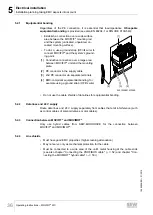
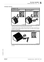
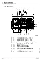
5.3.8
Plug connectors
All MOVIFIT
®
plug connectors are illustrated in these operating instructions with view
on the contact end.
5.3.9
Protection devices
MOVIFIT
®
drives have integrated protection devices against overloads. External over-
load devices are not necessary.
5.3.10
Installation altitude higher than 1000 m above sea level
MOVIFIT
®
units with supply voltages of 380 to 500 V can be used at altitudes above
1000 up to 4000 m above sea level. To do so, you must observe the following basic
conditions.
• At heights above 1000 m above sea level, the nominal continuous power is re-
duced due to reduced cooling: I
N
reduction by 1% per 100 m.
• At altitudes of 2000 to 4000 m above sea level you must take limiting measures
which reduce the line side overvoltage from category III to category II for the entire
system.
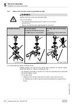
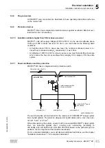
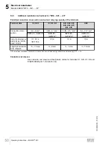
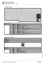
5.3.11
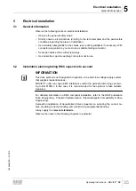
Power distribution and line protection
MOVIFIT
®
MC has an integrated motor protection switch.
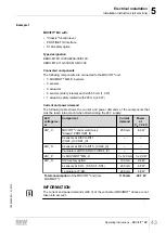
Power bus (max. 6 mm²)
MOVIMOT
®
1
MOVIMOT
®
2
MOVIMOT
®
3
3 MOVIMOT
®
hybrid
line cables
Line terminal (X1)
MOVIFIT
®
-MC
Load interrupter switch
and line protection
9007200274584715
The switch provides joint protection for the maximum of 3 MOVIMOT
®
supply system
lines (hybrid cables). The switch is designed for hybrid cables with a core cross sec-
tion of 1.5 mm
2
or 2.5 mm
2
.
When dimensioning the system, ensure that the connected MOVIMOT
®
supply system
lines are protected against short circuiting and overloading (according to
IEC 60364
‑
4
‑
43, HD 60364
‑
4
‑
43, DIN VDE 0100
‑
430) based on the particular grid im-
pedance, the line lengths and the transition resistances.
For UL-compliant installation, you must observe additional restrictions; see the chapter
"Installation instructions" > "UL-compliant installation".
19484828/EN – 01/2015


