


24
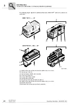
Operating Instructions – MOVIFIT® FDC
4
Mounting
Mechanical Installation
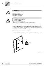
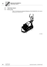
4.3
Mounting
4.3.1
Mounting rail
MOVIFIT
®
FDC is equipped with a mounting rail to attach the unit to a level, low-vibra-
tion mounting surface using screws of size M6.
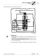
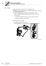
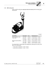
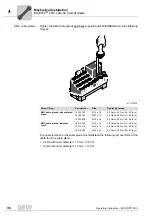
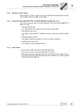
For bore dimensions of the respective type of fixture, see the following figures.
Drilling template for the standard mounting rail
You find detailed dimension drawings in the "Dimension drawings" (page 115) chapter.
9007202299435147
66
334.5
303.5
280
140
37,9
min. 40
15
min. 50
[1]
[2]
7.0 (6x)
13.9 (6x)
INFORMATION
• [1] Observe the minimum installation clearance so that the EBOX can be removed
from the ABOX.
• [2] Observe the minimum installation clearance required to operate the mainte-
nance switch and to ensure heat dissipation for the unit.
• Make sure that the permitted bending radii of the cables used are not exceeded
when connecting the cables.
Содержание MOVIFIT FDC
Страница 2: ...SEW EURODRIVE Driving the world...
Страница 137: ...Operating Instructions MOVIFIT FDC 137 Index Y Y adapter 77 0 9 24 V terminals connection 55...
Страница 138: ......
Страница 139: ......