68
Operating Instructions – MOVIDRIVE® MDR60A/61B
6
Explanation of the parameters
MDR61B1600/2500 – Parameters
6.2
Explanation of the parameters
The parameters are explained below. The parameters are divided into 10 groups. The
parameter names correspond to their representation in the parameter tree. The factory
setting is underlined.
6.2.1
Symbols
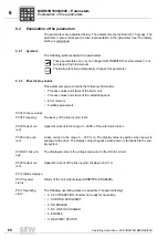
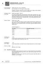
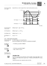
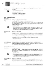
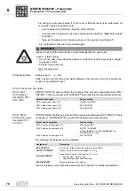
The following symbols explain the parameters:
6.2.2
P0xx display values
This parameter group contains the following information:
• Process values and states of the basic unit
• Process values and states of the installed options
• Error memory
• Fieldbus parameters
P00x Process values
P002 Frequency
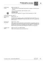
Frequency of the line inverter in Hz.
P004 Output cur-
rent
Apparent current in the range 0 – 200% of the rated unit current.
P005 Active cur-
rent
Active current in the range 0 – 200 % I
N
. The display value is positive when power is
supplied to the drive. The display value is negative when power is fed back into the sup-
ply system.
P008 DC link volt-
age
The displayed value is the voltage measured in the DC link circuit.
P009 Output cur-
rent
Apparent current of the line inverter, displayed in AC A.
P01x Status displays
P010 Inverter
status
Status of the unit output stage (INHIBITED, ENABLED).
P011 Operating
state
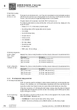
The following operating states are possible (7 segment display):
• 0: 24 V OPERATION (inverter not ready for operation)
• 1: CONTROLLER INHIBIT
• 2: NO ENABLE
• 3: DC LINK IS CHARGED
• 4: ENABLE
• 8: DELIVERY STATUS
These parameters can only be changed with INHIBITED inverter status (= out-
put stage at high resistance).
The startup function automatically changes this parameter.
AUTO
P
i
f
kVA
Hz
n
Содержание MDR60A
Страница 2: ...SEW EURODRIVE Driving the world...
Страница 145: ......
Страница 146: ......
Страница 147: ......

