SEW DRC.-...-DAC Скачать руководство пользователя страница 184

184

Operating Instructions – Electronic Motor DRC.-..-DAC

10

Releasing the brake without drive enable signal

Operation

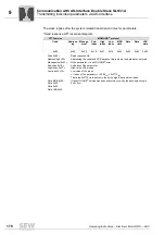
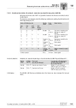
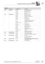
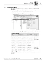
10.3.4 Functional description automatic mode (bus mode) with GLK31A double slave 

When switch S1/2 is set to "ON", it is possible to release the brake even without a drive
enable signal.

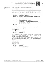
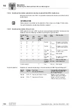
10.3.5 Functional description of local mode 

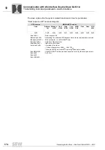
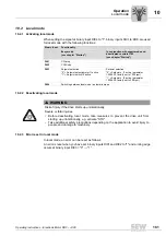
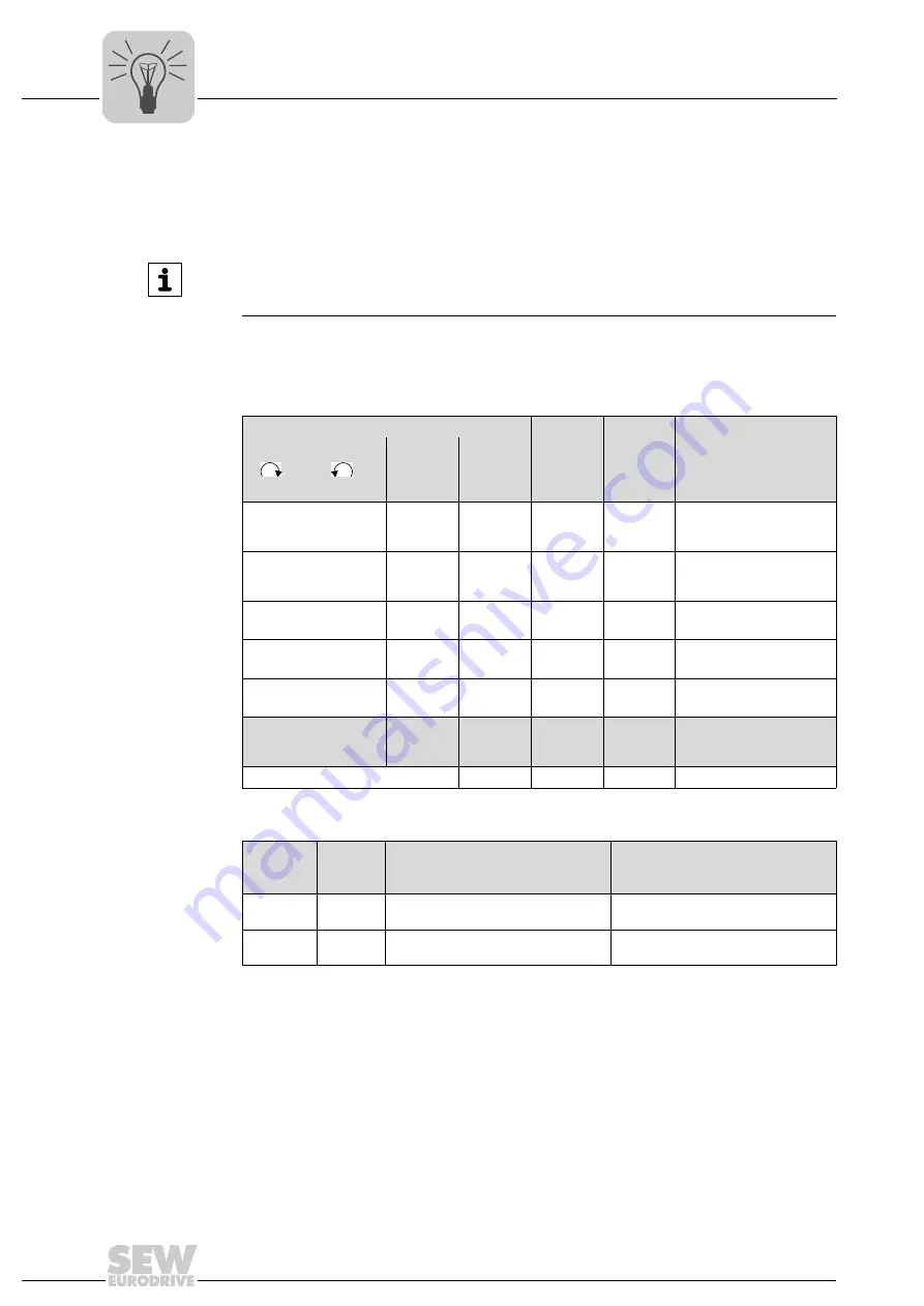
If DIP switch S1/2 is set to "ON" and local mode is activated with DI04, the brake can be
released under the following conditions by setting the signal at DI03:

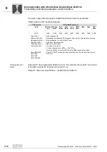
Setpoint selection

Setpoints are selected depending on the AS-Interface bit DO2 "Speed f2/Speed f1".

INFORMATION

Brake release is controlled via the data bits of the A-slave, see chapter "Communica-
tion with AS-Interface double slave/function modules". 

Terminal status

Unit 
status

Error 
status

Brake function

DI01

DI02

DI03
f1/f2

DI04 
automatic
/local 
mode

"1"
"0"

"0"
"1"

"0"

"1"

Enabled

No 
unit error

The brake is controlled by 
the DRC inverter, setpoint 
f1 

"1"
"0"

"0"
"1"

"1"

"1"

Enabled

No 
unit error

The brake is controlled by 
the DRC inverter, setpoint 
f2

"1"

"1"

"0"

"1"

No enable 
signal

No 
unit error

The brake is controlled by 
the DRC inverter

"0"

"0"

"0"

"1"

No enable 
signal

No 
unit error

Brake applied

"1"

"1"

"1"

"1"

No enable 
signal

No 
unit error

The brake is controlled by 
the DRC inverter

"0"

"0"

"1"

"1"

Control-
ler inhibit 
or STO

No 
unit error

Brake is released for 
manual operation

All states possible

"1"

Error

Unit error

Brake applied

Enable 
status

AS-Inter-
face bit

Easy mode 
(see chapter "Startup")

In conjunction with expert mode 
and deactivated controls f1/f2
(see chapter "Startup")

Enabled

DO2 = "0" Setpoint potentiometer f1 active

Setpoint n_f1 active (parameter 
10096.35, factory set to 1500 rpm)

Enabled

DO2 = "1" Setpoint switch f2 active

Setpoint n_f2 active (parameter 
10096.36, factory set to 200 rpm)

Содержание DRC.-...-DAC

Страница 1: ...Drive Technology Drive Automation System Integration Services Operating Instructions Electronic Motor DRC DAC Direct AS Interface Communication Edition 02 2012 19376014 EN...

Страница 2: ...SEW EURODRIVE Driving the world...

Страница 3: ...3 3 Example nameplate and type designation of drive units 14 3 4 Electronics 15 3 5 Example nameplate and type designation of electronics 18 3 6 DRC drive units in ASEPTIC ASEPTICplus design 20 4 Mec...

Страница 4: ...ers of the command PCB 105 8 2 Overview of power section parameters 109 8 3 Description of command PCB parameters 118 8 4 Description of power section parameters 127 9 Communication with AS Interface...

Страница 5: ...tervals 201 12 3 Inspection and maintenance work 202 13 Technical Data and Dimension Sheets 204 13 1 Technical data 204 13 2 Braking resistors 208 13 3 Technical data of the brake 220 13 4 ASEPTIC ASE...

Страница 6: ...damage to property and other notes 1 2 2 Structure of the section related safety notes Section related safety notes do not apply to a specific action but to several actions pertaining to one subject...

Страница 7: ...tation to ensure safe operation and to achieve the specified product characteristics and performance features SEW EURODRIVE assumes no liability for injury to persons or damage to equipment or propert...

Страница 8: ...the event of damage During operation DRC drive units can have live bare and movable or rotating parts as well as hot surfaces depending on their degree of protection Removing covers without authorizat...

Страница 9: ...nection requirements as provided on the nameplate and in the documentation 2 3 1 Safety functions DRC drive units may not perform safety functions unless these functions are described and expressly pe...

Страница 10: ...or due to the kinetic energy of the system machine Secure the output shaft against rotation before opening the wiring compartment Electrical installation must be carried out in compliance with pertine...

Страница 11: ...because some capacitors might still be charged Wait at least for 10 minutes after the supply voltage has been switched off The connection boxes must be closed and screwed on before the supply voltages...

Страница 12: ...ucture 3 1 DRC drive unit The following figure depicts drive units consisting of DRC1 DRC2 electronic motor and R gear unit 4761500555 1 Electronics cover 2 DRC electronic motor with connection unit 3...

Страница 13: ...uipped with the following cable entries1 Position X 2 3 X 2 x M25 x 1 5 2 x M16 x 1 5 2 2 x M25 x 1 5 2 x M16 x 1 5 3 2 x M25 x 1 5 2 x M16 x 1 5 1 1 x M16 x 1 5 reserved for pressure compensation fit...

Страница 14: ...ith a period as separator 1 2 76646 Bruchsal Germany kg AMB 1845 494 1 50 C MA MBR Ma pk Nm IM Nm Nm i kW Iso Kl M L Hz 50 60 V A nR r min IP eff 26 000 85 0 04 TENV 87 1 IE4 1 04 156 20 40 Made in Ge...

Страница 15: ...ug connector connection unit for DRC electronics cover 6 AS Interface sensors 7 DRC electronics cover 8 Electronics cover nameplate 9 DIP switches S1 1 S1 4 10 DIP switches S2 1 S2 4 11 Cable glands 1...

Страница 16: ...itional sensor signals to the AS Interface master The acyclic parameter bits are used to select speed scaling factors GLK31A double slave The GLK31A option works as a double slave on the AS Interface...

Страница 17: ...nics Unit Structure 3 4 3 Electronics cover outside The following figure shows the outside of the electronics cover 9007201622609547 1 Setpoint potentiometer f1 underneath the gland 2 Diagnostic inter...

Страница 18: ...pe designation refer to chapter Type designation 3 5 2 Type designation of electronics cover The following table shows the type designation of the electronics cover 4766269963 1 Nameplate of connectio...

Страница 19: ...he following table shows the type designation of the connection unit D R C 1 5 0 3 DAC A GLK30A Connection unit option GLK30A GLK30A binary slave GLK31A GLK31A double slave DRC version DRC installatio...

Страница 20: ...rotection IP66 and incompatibility with cleaning agents Possible damage to property To achieve degree of protection IP66 and compatibility with cleaning agents you have to replace the plastic screw pl...

Страница 21: ...atures of gear units in ASEPTICplus design Available for gear units with solid shaft hollow shaft with key or TorqLOC for the following gear unit sizes R27 87 F27 87 K37 87 and W37 Gear unit output sh...

Страница 22: ...isk of injury Adhere to the notes about installation and disassembly Before releasing shaft connections make sure that there are no active torsional moments present tensions within the system WARNING...

Страница 23: ...nical data and dimension sheets Lubricants The drive must not be assembled in the following ambient conditions Potentially explosive atmosphere Oils Acids Gases Vapors Radiation For special designs Th...

Страница 24: ...e motor shafts Observe the permitted overhung and axial loads specified in the DRC Gear motors catalog Do not jolt or hammer the shaft end Ensure that cooling air supply is unobstructed and that air d...

Страница 25: ...to remove the DRC electronics cover For detailed dimension drawings see chapter Technical data and dimension sheets WARNING Burns caused by hot surfaces Severe injuries Let the units cool down before...

Страница 26: ...e to the paint work if necessary Observe the notes in chapter Drive units with optional ASEPTIC ASEPTICplus design 4 4 4 Painting drive units NOTICE Breather valves and oil seals may be damaged during...

Страница 27: ...Installation 4 5 Tightening torques 4 5 1 Blanking plugs Tighten the blanking plugs included in the delivery with 2 5 Nm Example The following figure shows an example WARNING Burns caused by hot surf...

Страница 28: ...le gland Cable with outer diameter from 4 to 8 mm Min 24 N Cable with outer diameter from 8 to 11 mm Min 34 N Cable with outer diameter from 11 to 16 mm Min 44 N Example The following figure shows an...

Страница 29: ...ctions Electronic Motor DRC DAC 29 4 Tightening torques Mechanical Installation 4 5 3 DRC electronics cover Tighten the screws on the DRC cover using 6 0 Nm working diagonally across 9007203306627211...

Страница 30: ...k the condition of the gaskets as well as the tightening torques of the screw fittings If damaged Consult SEW EURODRIVE Make sure to install the cables with a drip loop Use only stainless steel cable...

Страница 31: ...lace ment of the plastic screw plugs supplied as standard with suitable stainless steel screw fittings 4768361227 1 The delivered plastic screw plugs must be replaced by suitable screw plugs made of s...

Страница 32: ...TIC ASEPTICplus design must only be used in the mounting position specified in the order Mounting position M1 M2 M3 M4 M5 M6 Cable entries Position 3 not permitted for M4 mounting position Position 2...

Страница 33: ...in the delivery by SEW EURODRIVE with 2 5 Nm Example The following figure shows an example The number and position of cable entries depends on the variant you have ordered WARNING Burns caused by hot...

Страница 34: ...nical Installation DRC electronics cover Proceed as follows when installing the DRC electronics cover Steps 1 Fix the DRC cover in position on the connection box with a tightening torque of 2 Nm 2 Tig...

Страница 35: ...om the cable gland Cable with outer diameter 10 mm 160 N Cable with outer diameter 10 mm 100 N Example The following figure shows an example The number and position of cable entries depends on the var...

Страница 36: ...CE typical drive system These operating instructions contain further information 5 1 3 Cable selection routing and shielding For more information on cable selection routing and shielding refer to cha...

Страница 37: ...over a wide surface area between the DRC drive unit and the mounting rail To do so use a ground strap HF litz wire for example to connect the DRC drive unit and the plant s grounding point Example Do...

Страница 38: ...pply system Cable cross section According to input current Iline at rated power see chapter Technical data and dimension sheets Install line fuses at the beginning of the power supply cable behind the...

Страница 39: ...nd sleeve with or without insulating shroud Connection cross section mm2 0 08 mm2 4 0 mm2 0 25 mm2 2 5 mm2 Connection cross section AWG AWG28 AWG12 AWG 23 AWG 14 Stripping length 8 mm 9 mm Control ter...

Страница 40: ...actuation Adhere to the following sequence when actuating the line terminals 5 2 5 Control terminal actuation Adhere to the following sequence when actuating the control terminals Terminals for the br...

Страница 41: ...ation button Connect the conductor after pressing the actuation button 9007201633209867 9007201633229835 Single wire conductors and flexible conductors with conductor end sleeves can be installed dire...

Страница 42: ...above note in accordance with EN 61800 5 1 5 2 8 Line contactor Use only a contactor of utilization category AC3 EN 60947 4 1 as a line contactor WARNING Electric shock due to incorrect earth leakage...

Страница 43: ...n cable with a minimum cross section of 10 mm2 or installing a second PE connection cable in parallel with the original PE connection WARNING Electric shock due to incorrect connection of PE Severe or...

Страница 44: ...rvoltage protection to limit overvoltage peaks to 2 5 kV phase to phase and phase to ground If safe electrical disconnection is required it must be implemented outside the unit for altitudes of 2000 m...

Страница 45: ...cuit protection does not provide branch circuit protection Branch circuit protection must be provided in accordance with the National Electrical Code and any additional local codes The table below lis...

Страница 46: ...orque X2 line terminals 1 L1 Brown Line connection phase L1 IN 2 L2 Black Line connection phase L2 IN 3 L3 Gray Line connection phase L3 IN 11 L1 Brown Line connection phase L1 OUT 12 L2 Black Line co...

Страница 47: ...14 24V_O DC 24 V output 15 0V24_O 0V24 reference potential output 21 n c Not assigned 22 DI01 Binary input DI01 23 DI02 Binary input DI02 24 DI03 Binary input DI03 25 DI04 Binary input DI04 X1 commun...

Страница 48: ...ated 24 V supply 3 CW stop 4 CCW stop 5 Setpoint changeover f1 f2 6 Automatic mode local mode 7 Signal relay contact closed ready for operation 8 Assignment see chapter Plug connector assignment 9 Bra...

Страница 49: ...les or hybrid cables outer shield A2 Conductive film 2 x pieces of conductive film to wind around the braid shield Use the conductive film if required B Installation material for control cables and da...

Страница 50: ...e routing and shielding Electrical Installation 5 5 2 General installation options The following figure shows the general installation options The following chapters show common examples and contain i...

Страница 51: ...not be used for mechanical protection of the cable Cable shield external braking resistor Connect the cable shield of the cable for an external braking resistor to the metal housing of the unit using...

Страница 52: ...nstallation Recommended cable routing The following figure shows the recommended cable routing Alternative cable routing The following figure shows the alternative cable routing 4731717771 Line voltag...

Страница 53: ...n alternative to using shield clamps for control cables STO binary signals you can use EMC cable glands which are available as an option to connect the shield 5 6 2 Assembly of EMC cable glands Fit th...

Страница 54: ...your order The number and type of required connection cables depend on the design of the units and the components to be connected This is why not all cables in the list are actually required The follo...

Страница 55: ...ixed 3 right X4271 AS Interface communication interface1 1 Standard scope of delivery Yellow Fixed X X5011 AS Interface sensors 1 Black Fixed 2 X1203_1 AC 400 V connection 2 2 Plug connector X1203_1 i...

Страница 56: ...g variants 1 Straight plug connector variant 2 Right angle plug connector variant Once the mating connector has been plugged in the right angle connector can be adjusted without using additional tools...

Страница 57: ...lectronic Motor DRC DAC 57 5 Plug connectors Electrical Installation Example 9007203327550219 2 1 90 INFORMATION Only cable outlet on the side is possible with plug connector position 3 and right angl...

Страница 58: ...Connection of AS Interface data cable Connection type M12 4 pole male A coded Wiring diagram 2384154763 Assignment No Name Function 1 AS AS Interface data cable 2 res Reserved 3 AS AS Interface data...

Страница 59: ...they are energized Function AC 400 V connection for supplying the unit for looping through Connection type M23 SEW insert SpeedTec capable company Intercontec female coding ring Black protected again...

Страница 60: ...e Length installa tion type Cable cross section Operating voltage Part number 1 812 746 0 Variable 2 5 mm2 AC 500 V M23 coding ring Black M23 coding ring Black Part number 1 813 395 9 Halogen free Var...

Страница 61: ...812 748 7 Variable 4 mm2 AC 500 V M23 coding ring Black M23 coding ring Black Part number 1 813 397 5 Halogen free Variable 4 mm2 AC 500 V M23 coding ring Black M23 coding ring Black Part number 1 81...

Страница 62: ...contec female 0 coded Wiring diagram 2264820107 Assignment No Name Function 1 DI01 Binary input DI01 CW stop 2 DI02 Binary input DI02 CCW stop 3 DI03 Binary input DI03 setpoint f1 f2 4 DI04 Binary inp...

Страница 63: ...Connection of cables with open end The following table shows the conductor assignment of the cable with the following part number 1 174 145 7 Signal name Color coding DI01 Pink DI02 Gray DI03 Red DI0...

Страница 64: ...njuries Do not use the 24 V output pins 1 and 3 for safety related applications with DRC drive units You may only jumper the STO input with 24 V when the DRC drive unit need not fulfill any safety fun...

Страница 65: ...12 739 8 INFORMATION Use only shielded cables for this connection and only suitable plug connectors that connect the shield with the unit in an HF capable manner Connection cable Length Installation t...

Страница 66: ...OUT The following table informs about this connection Function Connection for safe torque off STO for looping through Connection type M12 5 pole male A coded Wiring diagram 2264818187 Assignment No Na...

Страница 67: ...ble for this connection INFORMATION Use only shielded cables for this connection and only suitable plug connectors that connect the shield with the unit in an HF capable manner Connection cable Length...

Страница 68: ...DRC drive unit The STO jumper plug deactivates the safety functions of the DRC drive unit The following figure shows the STO jumper plug part number 1 174 709 9 WARNING Safe disconnection of the DRC...

Страница 69: ...ially available PC laptop 1 using one of the following options 3 PEAK CAN dongle with adapter cable Part number of PEAK CAN dongle 1821 0597 Part number of adapter cable 1812 3864 2 Interface adapter...

Страница 70: ...electronics cover switch off the power to the DRC drive units using a suitable external disconnecting device Secure the drive unit against unintended re connection to the voltage supply Secure the ou...

Страница 71: ...lly and electrically Appropriate safety measures prevent the drives from starting up unintentionally Appropriate safety measures must be taken to prevent risk of injury or damage to the machine INFORM...

Страница 72: ...wing figure gives an overview of control elements on the DRC electronics cover 9007201645995019 1 DIP switches S1 S2 Switch t1 Switch f2 2 Setpoint potentiometer f1 underneath the gland 3 Diagnostic i...

Страница 73: ...the ensured degree of protection if the screw plugs of the f1 setpoint potentiometer are not installed or not installed correctly Damage to the DRC electronics cover Once you have set the setpoint mak...

Страница 74: ...tches use only suitable tools such as a slotted screwdriver with a blade width of no more than 3 mm The force used for setting the DIP switches must not exceed 5 N 2391265547 34567 34567 ON ADE04SA 1...

Страница 75: ...available You can use the MOVITOOLS MotionStudio software to adjust the parameters to the application DIP switch S2 3 Direction of rotation reversal You can reverse the direction of rotation of the d...

Страница 76: ...t the DIP switches use only suitable tools such as a slotted screwdriver with a blade width of no more than 3 mm The force used for setting the DIP switches must not exceed 5 N 5 Set the 1st speed at...

Страница 77: ...requirements must be met The new DRC drive unit with AS Interface must have the address 0 If you replace several DRC drive units with AS Interface you must replace them individually one after the oth...

Страница 78: ...erface AS Interface bit Function DO0 CW stop DO1 CCW stop DO2 Speed f2 speed f1 DO3 Reset1 controller enable 1 In the event of an edge change 0 1 only effective in case of an error INFORMATION To enab...

Страница 79: ...000 rpm Setting f1 1000 rpm 1 1 1 1 1 00 2000 1000 1 1 1 0 1 11 1800 900 1 1 0 1 1 25 1600 800 1 1 0 0 1 43 1400 700 1 0 1 1 1 67 1200 600 1 0 1 0 2 00 1000 500 1 0 0 1 2 22 900 450 1 0 0 0 2 50 800 4...

Страница 80: ...ed by using unsuitable tools Possible damage to property To set the DIP switches use only suitable tools such as a slotted screwdriver with a blade width of no more than 3 mm The force used for settin...

Страница 81: ...w plug of the diagnostic interface has a seal and screw it in 15 Switch on the following voltages AS Interface voltage Line voltage 16 Set the required AS Interface address With a hand held programmin...

Страница 82: ...rements must be met The new DRC drive unit with AS Interface must have the address 0 If you replace several DRC drive units with AS Interface you must replace them individually one after the other Man...

Страница 83: ...verter to the voltage supply 5 Start MOVITOOLS MotionStudio 6 Create a project and network 7 Configure the communication channel at the PC 8 Perform an online scan You will get the following or a simi...

Страница 84: ...eter setpoint 855 rpm 12 Disconnect the PC from the DRC inverter 13 Make sure the screw plug of the diagnostic interface has a seal and screw it in NOTICE Loss of the ensured degree of protection if t...

Страница 85: ...to the AS interface plug connector of the DRC drive unit see the following figure 6 8 1 X4271 AS Interface communication interface The following table informs about this connection NOTICE Damage to th...

Страница 86: ...tartup 6 8 2 Example Disconnect the AS Interface nodes from the AS Interface network one at a time and assign addresses via the hand held programming device A Then reconnect the respective AS Interfac...

Страница 87: ...properly Observe chapter Electrical Installation 5 Place the DRC electronics cover onto the connection box and screw it on 6 Switch on the following voltages AS Interface voltage Line voltage 7 Set t...

Страница 88: ...it with AS Interface option GLK31A must have the address 0 If you replace several DRC drive units with AS Interface option GLK31A you must replace them individually one after the other Manual address...

Страница 89: ...face plug connector of the DRC drive unit see the following figure X4271 AS Inter face communica tion interface The following table informs about this connection NOTICE Damage to the units caused by f...

Страница 90: ...e Disconnect the AS Interface nodes from the AS Interface network one at a time and assign addresses via the hand held programming device A Then reconnect the respective AS Interface node to the AS In...

Страница 91: ...uired 9 Disconnect the PC from the DRC inverter 10 Make sure the screw plug of the diagnostic interface has a seal and screw it in NOTICE Loss of the ensured degree of protection if the screw plug of...

Страница 92: ...tudio 5 Create a project and network 6 Configure the communication channel at the PC 7 Perform an online scan You will get the following or a similar result 8 Open the context menu of the DRC command...

Страница 93: ...855 rpm 11 Disconnect the PC from the DRC inverter 12 Make sure the screw plug of the diagnostic interface has a seal and screw it in NOTICE Loss of the ensured degree of protection if the screw plug...

Страница 94: ...unication options You can operate up to four communication channels at the same time MOVITOOLS MotionStudio supports the following types of communication channels Serial RS 485 via interface adapters...

Страница 95: ...MotionStudio 2 Create a project with a name and directory 7 2 2 Establishing communication and scanning the network Proceed as follows to establish a communication with MOVITOOLS MotionStudio and sca...

Страница 96: ...network view 2 Right click to open the context menu and display the tools for configuring the unit The example shows the context menu with the tools for a DRC power section 2 The communication mode is...

Страница 97: ...tes the two types of tools 4710632331 1 Hard drive of the engineering PC 2 RAM of the engineering PC 3 Engineering PC 4 Unit 1 HDD R A M 3 2 4 R A M Offline Tool Online Tool Tools Description Offline...

Страница 98: ...the tools for configuring the unit INFORMATION The online connection status is NOT a response message which informs you that you are currently connected to the unit or that your unit is ready for comm...

Страница 99: ...ribes how to connect the PC CAN interface from SEW to the SBus interface or your units and what must be considered for this Connecting the USB CAN inter face to the unit The figure shows how the USB C...

Страница 100: ...ce for this purpose Proceed as follows to configure an SBus connection 1 Click on Configure communication connections 1 in the toolbar This will open the Configure communication connections window 2 F...

Страница 101: ...on 3 on the right side of the Configure communication connections window This will display the settings for the SBus communication type 4 It might be necessary to change the preset communication param...

Страница 102: ...Adjustable values permitted total cable length 500 kBd 50 m Default 1 MBd 25 m All connected units must support the same baud rate Communication parameters Description Information Parameter telegrams...

Страница 103: ...anging unit parameters Proceed as follows to read or change unit parameters 1 Switch to the required view project view or network view 2 Select the connection mode Click the Switch to online mode butt...

Страница 104: ...e units online Do the following to start up the units online 1 Switch to the network view 2 In the toolbar click on Switch to online mode 1 3 Select the unit you want to start up 4 Open the context me...

Страница 105: ...1 2 10 Command PCB parameters display values analog setpoints 10096 28 Setting of setpoint potentiometer f1 0 10 1 digit 0 001 Command PCB parameters display values binary inputs 8334 0 bit 1 Binary i...

Страница 106: ...t bit DI0 Bit field Ready message 9866 1 bit 1 AS Interface input bit DI1 Bit field Automatic manual mode 9756 1 bit 6 AS Interface output bit DI2 Bit field Sensor output 1 9756 1 bit 7 AS Interface i...

Страница 107: ...11 down 0 00 1 00 60 00 s 1 digit 0 001 s Only in conjunction with AS Interface binary slave GLK31A 10504 1 Ramp t15 up 0 00 1 00 60 00 s 1 digit 0 001 s 10504 11 Ramp t15 down 0 00 1 00 60 00 s 1 dig...

Страница 108: ...50 00 2000 00 rpm 1 digit 0 001 rpm 8491 0 Fixed setpoint n2 2000 00 1500 00 2000 00 rpm 1 digit 0 001 rpm 10096 31 Fixed setpoint n3 2000 00 2000 00 rpm 1 digit 0 001 rpm 10096 38 Fixed setpoint n4 2...

Страница 109: ...digit 0 001 9872 255 Motor temperature C 1 digit 10 6 C Power section parameters display values unit status Unit status 9702 2 Power section status Text 9702 7 Drive status Text 9702 5 Error code Tex...

Страница 110: ...01 8421 0 DC link voltage t 0 V 1 digit 0 001 V Unit status 8391 0 Power section status t 0 Text 8426 0 Operating hours t 0 h 1 digit 1 min 1 60 h 8431 0 Enable hours t 0 h 1 digit 1 min 1 60 h 10083...

Страница 111: ...Operating hours t 2 h 1 digit 1 min 1 60 h 8433 0 Enable hours t 2 h 1 digit 1 min 1 60 h 10083 3 Work t 2 kWh 1 digit 1Ws 1 3600000 Temperatures 8398 0 Heat sink temperature t 2 C 1 digit 1 C 10070...

Страница 112: ...Actual speed t 4 rpm 1 digit 0 001 rpm 8410 0 Apparent output current t 4 1 digit 0 001 8415 0 Active output current t 4 1 digit 0 001 8420 0 Unit utilization t 4 1 digit 0 001 8445 0 Motor utilizatio...

Страница 113: ...nerators setpoint monitoring Setpoint stop function 8578 0 Setpoint stop function 0 Off 1 On 8579 0 Stop setpoint 160 500 rpm 1 digit 0 001 rpm 8580 0 Start offset 0 30 500 rpm 1 digit 0 001 rpm Power...

Страница 114: ...on parameters drive data monitoring functions Speed monitoring 8557 0 Speed monitoring 0 Off 1 Motor mode 2 Regenerative mode 3 Motor regenerative 8558 0 Speed monitoring delay time 0 00 1 00 10 00 s...

Страница 115: ...01 status signal relay K1 Bit field 8350 0 Binary output DO01 function signal relay K1 0 No function 1 Fault 2 Ready 3 Output stage ON 4 Rotating field ON 5 Brake released 6 Brake applied 7 Motor stan...

Страница 116: ...it 0 001 rpm 8545 0 Deceleration time 0 1 9 s 1 digit 0 001 s 8546 0 Signal 1 if 0 internal 1 external Speed setpoint actual value comparison 8547 0 Hysteresis 1 100 300 rpm 1 digit 0 001 rpm 8548 0 D...

Страница 117: ...ency stop waiting 7 Stop waiting 9729 4 Line phase failure response 0 No response 1 Display only 2 Output stage inhibit locked 3 Emergency stop locked 4 Stop locked 5 Output stage inhibit waiting 6 Em...

Страница 118: ...setting of switch f2 Display of the switch setting is independent of whether the switch function is activated or deactivated Parameter setting of switch t1 index 10096 29 The parameter indicates the...

Страница 119: ...state of binary input DI03 Binary input DI04 index 8334 0 bit 4 The parameter indicates the state of binary input DI04 Binary input DI01 index 8335 0 The parameter indicates the function of binary inp...

Страница 120: ...y it in the hardware tree or in other visualization elements Firmware AS Interface option index 9701 53 9701 54 The parameter indicates the part number and version of the firmware used in the AS Inter...

Страница 121: ...tion modules Parameter value Type of AS Interface option 0 AS Interface is not available 3 GLK30A binary slave 4 GLK31A double slave Index AS Interface bit Meaning 9756 1 bit 0 AS Interface output bit...

Страница 122: ...S Interface bus monitor They indicate the transmission of AS Interface bits from and to the DRC inverter The meaning of the AS Interface data bits depends on the selected function module see chapter F...

Страница 123: ...slave GLK31A the parameter is used to set the acceleration ramp for function modules 1 5 7 of the double slave Ramp t11 down index 8808 0 Use this parameter to set deceleration ramp t11 down Unit s Se...

Страница 124: ...amp t15 down depending on which function module is active Unit s Setting range 0 1 60 s The ramp times refer to a setpoint step change of n 3000 rpm Ramp t16 up index 10475 2 Only in conjunction with...

Страница 125: ...tors of the setpoint speed The setpoint scaling affects only the setpoint set using setpoint potentiometer f1 The current scaling factor is determined by the parameter bits see chapter Setpoint scalin...

Страница 126: ...ameters unit functions setup Factory setting index 8594 0 If you set this parameter to Delivery state all parameters that have a factory setting and can not be set using DIP switches t1 f2 or setpoint...

Страница 127: ...r rent index 8322 0 The parameter indicates the active current The display value is positive when torque is applied in the positive direction of rotation negative when torque is applied in negative di...

Страница 128: ...ndicates a pending error with error number in plain text Error and suberror code index 10071 1 The parameter provides detailed information on the error of an error group Error source index 10404 5 The...

Страница 129: ...204 2 The parameter indicates the DRC installation technology e g DBC Direct Binary Communication DAC Direct AS Interface Communication DSC Direct SBus Communication SNI Single Line Network Installati...

Страница 130: ...memories t 0 t 4 The errors are stored in a chronological sequence with the most recent error event being stored in error memory t 0 If there are more than 5 errors the error event of longest standin...

Страница 131: ...error Unit rpm Apparent output current t 0 4 index 8406 0 8407 0 8408 0 8409 0 8410 0 The parameter indicates the apparent output current in percent of the nominal unit current at the time of the erro...

Страница 132: ...e of the error Storage cycle every 15 min Unit h Enable hours t 0 4 index 8431 0 8432 0 8433 0 8434 0 8435 0 The parameter indicates the total number of hours for which the power section was in ENABLE...

Страница 133: ...nerators speed ramps Stop ramp t13 index 8476 0 This parameter is used to set stop ramp t13 Unit s Setting range 0 2 2000 s The stop ramp is active in the event of a power failure or an error paramete...

Страница 134: ...emergency stop ramp if speed monitoring is not desired Power section parameters setpoints integrators motor potentiometer Ramp t3 up down index 8486 0 8467 0 These parameters are used to set ramp t3...

Страница 135: ...he specific application and to be able to react in case of impermissible deviations You can set the response to triggered monitoring functions under Unit functions error monitoring Speed monitoring in...

Страница 136: ...The user specifies the current limit in IN based on the continuous apparent current of the power section The actually effective current limit calculated by the unit can be lower to protect the gear un...

Страница 137: ...cha tronic MOVIGEAR drive unit DynaStop is deactivated In conjunction with DRC electronic motor Brake applied In conjunction with DRC electronic motor Brake released 6 Brake applied1 In conjunction wi...

Страница 138: ...peed reference signal Signal if the speed is less than or greater than the set reference speed Speed reference value index 8539 0 Setting range 0 1500 6000 rpm Hysteresis index 8540 0 Setting range 0...

Страница 139: ...indow range Window center index 8543 0 Setting range 0 1500 6000 rpm Range width index 8544 0 Setting range 0 6000 rpm Delay time index 8545 0 Setting range 0 1 9 s Signal 1 if Index 8546 0 Setting ra...

Страница 140: ...f the speed is equal to or not equal to the setpoint speed Hysteresis index 8547 0 Setting range 1 100 300 rpm Delay time index 8548 0 Setting range 0 1 9 s Signal 1 if Index 8549 0 Setting range n ns...

Страница 141: ...ndex 8551 0 Setting range 0 5 30 IN Delay time index 8552 0 Setting range 0 1 9 s Signal 1 with index 8553 0 I Iref I Iref Imax signal Signal if the inverter has reached the current limitation Hystere...

Страница 142: ...brake remains open and the drive generates a holding torque 1 ON The drive decelerates along the set ramp When the speed is 0 the brake is applied Brake application for STO index 9833 20 The parameter...

Страница 143: ...peed control Limits Serial communication SBus 1 Speed task 1 2 Error memory Statistical data The delivery state setting also resets the data listed above Once the data has been reset parameter 8594 0...

Страница 144: ...voked and the error output is set if programmed A restart is only possible after an error reset during which the inverter is reinitial ized 4 STOP LOCKED The drive is braked along the set stop ramp t1...

Страница 145: ...NG Index 9729 9 is used to program the error response which is triggered by the tempera ture sensor monitoring function of the TF or TH which may be installed in the motor winding Manual reset index 8...

Страница 146: ...2 P0 are used for switching between the individ ual function modules These parameter bits determine the meaning of the data bits In the extended address mode the fourth parameter bit is not available...

Страница 147: ...OVILINK protocol parameter telegram via the SBus interface of the inverter The DRC inverter transmits the response telegram to the GLK31A option via the SBus interface The GLK31A option converts the r...

Страница 148: ...n function modules 0hex 1hex are selected all 4 data bits DI0 DI3 are trans mitted from the slave to the master according to the DRC status word The state of the sensor inputs is not transmitted AS In...

Страница 149: ...put data AS Interface master GLK31A option Function module 7hex AS interface parameter bits 111bin Data bit A slave Function DO0 CW stop DO1 CCW stop DO2 Setpoint changeover f1 f2 DO3 Reset1 controlle...

Страница 150: ...xed setpoint n2 8491 0 Ramps t11 up 8807 0 t11 down 8808 0 1000bin 8dec CW operation fixed setpoint n3 1096 31 Ramps t11 up 8807 0 t11 down 8808 0 1001bin 9dec CCW operation fixed setpoint n3 1096 31...

Страница 151: ...in 6dec CW operation fixed setpoint n2 8491 0 Ramps t15 up 10504 1 t15 down 10504 11 0111bin 7dec CCW operation fixed setpoint n2 8491 0 Ramps t15 up 10504 1 t15 down 10504 11 1000bin 8dec CW operatio...

Страница 152: ...1 0110bin 6dec CW operation fixed setpoint n2 8491 0 Ramps t16 up 10475 2 t16 down 10475 1 0111bin 7dec CCW operation fixed setpoint n2 8491 0 Ramps t16 up 10475 2 t16 down 10475 1 1000bin 8dec CW ope...

Страница 153: ...Ramps t11 up 8807 0 t11 down 8808 0 1010bin 10dec CW operation Fixed setpoint n4 10096 38 Ramps t11 up 8807 0 t11 down 8808 0 1011bin 11dec CCW operation Fixed setpoint n4 10096 38 Ramps t11 up 8807 0...

Страница 154: ...c transmission This bit is not used for the parameter transmission with the GLK31A option Status bit 7 indicates whether the service was carried out properly or whether errors occurred Index addressin...

Страница 155: ...ype according to EN 50170 For unit variants with GLK31A the error class is 0x08 Error code 0x0 Error code For unit variants with GLK31A the error code is 0x00 Additional code High 0x0 For unit variant...

Страница 156: ...time for a parameter System related transmission times occur during data exchange between the DRC B slave and the AS Interface master using the CTT2 protocol These transmission times mainly depend on...

Страница 157: ...have to program fixed wait times when programming the higher level controller to compensate for transmission times for parameters The following chapters describe the individual CTT2 services A prerequ...

Страница 158: ...Read response not OK for error codes refer to the AS Interface specification Read request service The slave replies after the system related transmission times for parameters Read response OK response...

Страница 159: ...read access Example Changing the fixed setpoint value n4 parameter 10096 38 to 1000 rpm Exchange request service CTT2 service MOVILINK protocol Code Index Read length Write length Address ing Manage m...

Страница 160: ...0x5D 0x00 0x32 0x26 0x27 0x70 0x00 0x00 0x00 0x00 Code 0x5D Exchange request OK Addressing 0x00 Addressing the command PCB because this is where the parameter is stored Management 0x32 Write paramete...

Страница 161: ...setpoint value n4 parameter 10096 38 to 1000 rpm Write request service The slave replies after the system related transmission times for parameters Write response OK response telegram CTT2 service MO...

Страница 162: ...esponse of the DRC inverter concerning the previous change of the fixed setpoint value n4 parameter 10096 38 Read request service The slave replies after the system related transmission times for para...

Страница 163: ...p and t11 down to 0 5 s Fixed setpoint value n0 to 1000 rpm In addition the heat sink temperature is to be read Checking the communication Read out the ID object correctly to check proper communicatio...

Страница 164: ...2 MOVILINK parameter service Read length 0x09 Length of the MOVILINK response Write length 0x09 Length of the MOVILINK request Addressing 0x00 Addressing the command PCB because this is where the para...

Страница 165: ...x1D Exchange request Index 0x02 MOVILINK parameter service Read length 0x09 Length of the MOVILINK response Write length 0x09 Length of the MOVILINK request Addressing 0x00 Addressing the command PCB...

Страница 166: ...ngth 0x09 Length of the MOVILINK request Addressing 0x00 Addressing the command PCB because this is where the parameter is stored Management 0x32 Write parameter Subindex 0x00 Subindex of the paramete...

Страница 167: ...ILINK request Addressing 0x01 Addressing the power section because this is where the parameter is stored Management 0x31 Read parameter Subindex 0x00 Subindex of the parameter High index 0x20 High val...

Страница 168: ...ween AS Interface master and GLK31A Read request service The slave replies after the system related transmission times for parameters Read response OK response telegram INFORMATION Make sure that Expe...

Страница 169: ...parameter 10096 0 Read request service CTT2 service MOVILINK protocol Code Index Length Address ing Manage ment Sub index High index Low index MSB data Data Data LSB data 0x11 0x02 0x09 0x00 0x32 0x1...

Страница 170: ...data 0x50 0x00 0x32 0x1E 0x27 0x70 0x00 0x00 0x00 0x00 Code 0x50 Read response OK Addressing 0x00 Addressing the command PCB because this is where the parameter is stored Management 0x32 Write parame...

Страница 171: ...Address ing Manage ment Sub index High index Low index MSB data Data Data LSB data 0x11 0x02 0x09 0x00 0x32 0x00 0x22 0x67 0x00 0x00 0x01 0xF4 Code 0x11 Write request Index 0x02 MOVILINK parameter se...

Страница 172: ...ervice MOVILINK protocol Code Address ing Manage ment Sub index High index Low index MSB data Data Data LSB data 0x50 0x00 0x32 0x00 0x22 0x67 0x00 0x00 0x00 0x00 Code 0x50 Read response OK Addressing...

Страница 173: ...ess ing Manage ment Sub index High index Low index MSB data Data Data LSB data 0x11 0x02 0x09 0x00 0x32 0x00 0x21 0x29 0x00 0x0F 0x42 0x40 Code 0x11 Write request Index 0x02 MOVILINK parameter service...

Страница 174: ...a LSB data 0x50 0x00 0x32 0x00 0x21 0x29 0x00 0x00 0x00 0x00 Code 0x50 Read response OK Addressing 0x00 Addressing the command PCB because this is where the parameter is stored Management 0x32 Write p...

Страница 175: ...rotocol Code Index Length Address ing Manage ment Sub index High index Low index MSB data Data Data LSB data 0x11 0x02 0x09 0x01 0x31 0x00 0x20 0x87 0x00 0x00 0x00 0x00 Code 0x11 Write request Index 0...

Страница 176: ...onse OK Addressing 0x01 Addressing the power section because this is where the parameter is stored Management 0x31 Read parameter no MOVILINK error Subindex 0x00 Subindex of the parameter High index 0...

Страница 177: ...OLS MotionStudio software 1 First connect the PC to the DRC inverter 2 Start MOVITOOLS MotionStudio and integrate the DRC inverter in MOVITOOLS MotionStudio Refer to the chapter Operating MOVITOOLS Mo...

Страница 178: ...ror reset Deactivation Manual mode is deactivated When you click on the Deactivate manual mode button Or when you close the Manual mode window Or when you set parameter 8594 0 to delivery condition 90...

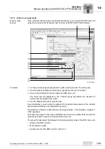
Страница 179: ...e motor axis 4 displayed in the Control group symbolizes the direction of rotation and the speed of the motor 4 Use the Stop button 7 to stop the drive As an alternative you can enter the setpoints fo...

Страница 180: ...If an error occurs at the DRC inverter you can reset the error by clicking on the Reset button 10 10 1 4 Timeout monitoring in manual mode Timeout monitoring is active during manual mode to prevent un...

Страница 181: ...r Startup In conjunction with expert mode and deactivated controls f1 f2 see chapter Startup DI01 CW stop DI02 CCW stop DI03 Setpoint selection 0 Setpoint potentiometer f1 active 1 Setpoint switch f2...

Страница 182: ...r hoist applications WARNING Electric shock caused by dangerous voltages in the connection box Dangerous voltages may still be present for up to 10 minutes after disconnection from the power supply sy...

Страница 183: ...f1 Reset enable 1 0 0 1 0 1 Enabled No unit error The brake is controlled by the DRC inverter setpoint f1 effective 1 0 0 1 1 1 Enabled No unit error The brake is controlled by the DRC inverter setpoi...

Страница 184: ...status Brake function DI01 DI02 DI03 f1 f2 DI04 automatic local mode R L 1 0 0 1 0 1 Enabled No unit error The brake is controlled by the DRC inverter setpoint f1 1 0 0 1 1 1 Enabled No unit error Th...

Страница 185: ...he brake has been released for manual mode WARNING Risk of injury if the drive starts up unintentionally Severe or fatal injuries Before deactivating local mode take measures to prevent the drive unit...

Страница 186: ...ng noise on motor Bearing damage Consult SEW EURODRIVE Service Replace motor Vibration of rotating parts Rectify cause possible imbalance Malfunction Possible cause Remedy Brake does not release Elect...

Страница 187: ...LS MotionStudio open the DRC parameter tree power section Observe chapter Operation of MOVITOOLS MotionStudio 2 In the parameter tree select the following node here for error memory t 0 for example Po...

Страница 188: ...igh resistance 11 3 3 Emergency stop The drive is decelerated using emergency stop ramp t14 When the stop speed is reached the brake is applied immediately if installed The output stage then goes to h...

Страница 189: ...Red green Flashing regularly Not ready Communication interrupted or peripheral error Yellow On Ready for operation Manual mode local mode active NET LED in conjunction with double slave GLK31A LED co...

Страница 190: ...tting parameters 97 IPOS error 10 Boot synchronization error 40 41 Safety error 119 More detailed diagnostic information via Drive LED DRIVE LED LED color LED status Operating state Description Off No...

Страница 191: ...error Error 25 NV memory error Error 27 29 Limit switch error Error 39 Reference travel error Error 42 Positioning lag error Error 94 Checksum error Error 97 Parameter transmission error Errors 10 32...

Страница 192: ...ics Emergency stop waiting Clean the heat sink Lower the ambient temperature Prevent heat build up Reduce the load on the drive Reset error by switching the unit off or via error reset function Error...

Страница 193: ...ether an option is installed Replace the option Error 42 Lag error positioning Output stage inhibit waiting Emergency stop ramp too short Extend emergency stop ramp P component of positioning controll...

Страница 194: ...n Error 89 Only in conjunction with DRC electronic motor Overtemperature in brake Output stage inhibit locked Brake coil not sufficient to dissipate the regenerative energy Use braking resistor Wrong...

Страница 195: ...ce option GLK30A GLK31A AS Interface output bits 9756 1 bit 0 AS Interface output bit DO0 CW operation stop Depending on the selected function module 9756 1 bit 1 AS Interface output bit DO1 CCW opera...

Страница 196: ...electronics cover onto the connection box and screw it on 6 Supply voltage to the drive 7 Check the functions of the new electronics cover WARNING Electric shock caused by dangerous voltages in the co...

Страница 197: ...and screw it on 8 Supply voltage to the drive 9 Parameters that can be changed are saved in the motor see Parameters chapter This means you have to change these parameters again when you replace the m...

Страница 198: ...Electrolytic capacitors are used in the inverters They are subject to aging effects when de energized This effect can damage the capacitors if the unit is connected using the nominal voltage after a l...

Страница 199: ...11 13 Disposal Observe the applicable regulations Dispose of the following materials in accordance with the regulations in force Aluminum scrap Housing parts Steel scrap Shafts Anti friction bearings...

Страница 200: ...performed operating hours of DRC drive units Proceed as follows to determine the performed hours of operation 1 In MOVITOOLS MotionStudio open the DRC parameter tree See chapter Config uration and dia...

Страница 201: ...external factors Touch up or renew the surface protection anticorrosion coating Qualified personnel at customer site If used as a holding brake Time interval What to do Who is permitted to perform the...

Страница 202: ...box Dangerous voltages may still be present for up to 10 minutes after disconnection from the power supply system Severe or fatal injuries Before removing the electronics cover de energize the DRC dr...

Страница 203: ...tion and maintenance 2 IMPORTANT Breather valves and oil seals may be damaged during painting or re painting Potential damage to property Clean the surface of the drive unit and make sure it is free f...

Страница 204: ...terference immunity EN 61800 3 2 Environment industrial environment Interference emission EN 61800 3 category C2 class A group 2 of EN 55011 Climate class EN 60721 3 3 class 3K3 Storage temperature S...

Страница 205: ...IE 10 mA sampling cycle 5 ms Number of inputs 4 Signal level 15 to 30 V 1 Contact closed 3 to 5 V 0 Contact open Signal relays Contact data K1a Response time 15 ms DC 24 V 50 mA DC 12 to IEC 60947 5 1...

Страница 206: ...IN motor reduction The following figure shows the IN motor reduction depending on the motor speed 9007202114032267 1 Ambient temperature 35 C 2 Ambient temperature 40 C Motor current I N motor 1000 10...

Страница 207: ...y Sensor inputs PLC compatible in accordance with EN 61131 2 Ri about 3 0 k IE about 10 mA Signal level 15 V to 30 V 3 V to 5 V 1 0 Maximum sensor cable length 15 m AS Interface GLK30A Protocol varian...

Страница 208: ...ive energy DRC1 2 electronic motor with brake Brake coil DRC1 2 electronic motor without brake Brake coil 1 1 Motors without brake are also equipped with a brake coil without brake disk to dissipate t...

Страница 209: ...ly within the unit which means it is mains independent 4Q operation with only the integrated brake coil is recommended for applications with very small amounts of regenerative energy If the amount of...

Страница 210: ...sistors Technical Data and Dimension Sheets BY2C DRC2 The following figure shows the permitted regenerative load on the BY2C brake coil DRC2 4989676939 c h cycles per hour 9000 0 1000 2000 3000 4000 5...

Страница 211: ...e and no longer consuming any more energy The inverter then trips with overvoltage error If the amount of regenerated energy is too high for the application you can use an external braking resistor as...

Страница 212: ...esistor for a brake ramp of 4 s Regenerative load capacity for a brake ramp of 0 2 s The following figure shows the permitted regenerative energy load of the BY1C brake coil in combination with the in...

Страница 213: ...th the integrated BW2 braking resistor for a brake ramp of 10 s Regenerative load capacity for a brake ramp of 4 s The following figure shows the permitted regenerative energy load of the BY2C brake c...

Страница 214: ...acity for a brake ramp of 0 2 s The following figure shows the permitted regenerative energy load of the BY2C brake coil in combination with the integrated BW2 braking resistor for a brake ramp of 0 2...

Страница 215: ...C2 BW K 1 5 BW T BW100 005 K 1 5 BW150 003 K 1 5 Part number 0 828 286 2 0 828 2927 Function Dissipating the regenerative energy Degree of protection IP65 IP65 Resistance 100 150 Power in S1 100 cdf 2...

Страница 216: ...figure shows the rating diagrams of the braking resistors BW100 005 K 1 5 BW150 003 K 1 5 Dimensiondrawing of BW150 003 K 1 5 The following figure shows the dimensions of the external braking resistor...

Страница 217: ...13 Braking resistors Technical Data and Dimension Sheets Dimensiondrawing of BW100 005 K 1 5 The following figure shows the dimensions of the external braking resistor BW100 005 K 1 5 4850166795 216 2...

Страница 218: ...rating diagrams of the braking resistors BW150 006 T and BW100 009 T Dimensiondrawing of BW150 006 T The following figure shows the dimensions of the external braking resistor BW150 006 T 4850239499 1...

Страница 219: ...AC 219 13 Braking resistors Technical Data and Dimension Sheets Dimensiondrawing of BW100 009 T The following figure shows the dimensions of the external braking resistor BW100 009 T 4850322059 75 160...

Страница 220: ...rations Braking work until maintenance Braking torque kJ MJ Nm BY1C 5 10 h 40 7 5 10 h 40 2 5 BY2C 15 10 h 65 14 15 10 h 65 7 NOTICE Damage to the DRC drive unit Potential damage to property Note that...

Страница 221: ...d by the company ECOLAB Alkaline and chlorinated alkaline foam cleaning agents Designation Application concentration Application temperature P3 topax 12 5 40 C Acid foam cleaning agents Designation Ap...

Страница 222: ...for environments prone to condensation and atmospheres with low humidity or contamination such as applications outdoors under roof or with protection Similar to corrosivity category C2 low Systems in...

Страница 223: ...changes1 Changes in protective properties1 P3 topax 19 Alkaline foam cleaning agent Alkalis surfac tants complexing agents 3 20 min 60 C 1 0 P3 topax 56 Acid foam cleansing agent Acids surfac tants i...

Страница 224: ...5 x 1 5 1 824 735 0 EMC cable gland nickel plated brass 10 pcs M16 x 1 5 1 820 478 3 10 pcs M25 x 1 5 1 820 480 5 EMC cable gland made of stainless steel 10 pcs M16 x 1 5 1 821 636 6 10 pcs M25 x 1 5...

Страница 225: ...7 1 DRC1 with IEC flange1 13 7 2 DRC2 with IEC flange1 4791750667 1 For gearmotor dimension sheets refer to the DRC Gearmotors catalog 4791754507 10 3 5 296 202 134 185 83 110j6 160 10 130 4 22 30 5...

Страница 226: ...chapter Electrical Installation Plug connector positions 18014401150429835 1 Straight plug connector variant 2 Right angle plug connector variant 13 16 11 5 52 51 55 72 501 55 72 3 4 1 2 5 6 7 8 1 X4...

Страница 227: ...adii of the optional plug connectors including mating connector in connection with prefabricated cables from SEW EURODRIVE For more information refer to chapter Electrical Installation Plug connector...

Страница 228: ...DUH LQ FRQIRUPLW ZLWK 0DFKLQHU LUHFWLYH RZ 9ROWDJH LUHFWLYH 0 LUHFWLYH SSOLHG KDUPRQL HG VWDQGDUGV 1 62 1 1 7KH SURGXFWV DUH LQWHQGHG IRU LQVWDOODWLRQ LQ PDFKLQHV 6WDUWXS LV SURKLELWHG XQWLO LW KDV EH...

Страница 229: ...9 909552 50 sc sued sew eurodrive de West SEW EURODRIVE GmbH Co KG Siemensstra e 1 D 40764 Langenfeld near D sseldorf Tel 49 2173 8507 30 Fax 49 2173 8507 55 sc west sew eurodrive de Electronics SEW E...

Страница 230: ...ve com au Sydney SEW EURODRIVE PTY LTD 9 Sleigh Place Wetherill Park New South Wales 2164 Tel 61 2 9725 9900 Fax 61 2 9725 9905 enquires sew eurodrive com au Austria Assembly Sales Service Wien SEW EU...

Страница 231: ...W EURODRIVE CHILE LTDA Las Encinas 1295 Parque Industrial Valle Grande LAMPA RCH Santiago de Chile P O Box Casilla 23 Correo Quilicura Santiago Chile Tel 56 2 75770 00 Fax 56 2 75770 01 http www sew e...

Страница 232: ...e cz sew sew eurodrive cz Denmark Assembly Sales Service Copenhagen SEW EURODRIVEA S Geminivej 28 30 DK 2670 Greve Tel 45 43 9585 00 Fax 45 43 9585 09 http www sew eurodrive dk sew sew eurodrive dk Eg...

Страница 233: ...a Registered Office Assembly Sales Service Vadodara SEW EURODRIVE India Private Limited Plot No 4 GIDC POR Ramangamdi Vadodara 391 243 Gujarat Tel 91 265 3045200 91 265 2831086 Fax 91 265 3045300 91 2...

Страница 234: ...acar inco com lb Jordan Kuwait Saudi Arabia Syria Beirut Middle East Drives S A L offshore Sin El Fil B P 55 378 Beirut Tel 961 1 494 786 Fax 961 1 494 971 info medrives com http www medrives com Lith...

Страница 235: ...Sales Service Moss SEW EURODRIVE A S Solgaard skog 71 N 1599 Moss Tel 47 69 24 10 20 Fax 47 69 24 10 40 http www sew eurodrive no sew sew eurodrive no Pakistan Sales Karachi Industrial Power Drives Al...

Страница 236: ...65 68612827 http www sew eurodrive com sg sewsingapore sew eurodrive com Slovakia Sales Bratislava SEW Eurodrive SK s r o Rybni n 40 SK 831 06 Bratislava Tel 421 2 33595 202 Fax 421 2 33595 200 sew se...

Страница 237: ...OREA Co Ltd No 1720 11 Songjeong dong Gangseo ku Busan 618 270 Tel 82 51 832 0204 Fax 82 51 832 0230 master sew korea co kr Spain Assembly Sales Service Bilbao SEW EURODRIVE ESPA A S L Parque Tecnol g...

Страница 238: ...east Region SEW EURODRIVE INC Pureland Ind Complex 2107 High Hill Road P O Box 481 Bridgeport New Jersey 08014 Tel 1 856 467 2277 Fax 1 856 845 3179 csbridgeport seweurodrive com Midwest Region SEW EU...

Страница 239: ...ding and Engineering Services A75 6B 12 Bach Dang Street Ward 02 Tan Binh District 70000 Ho Chi Minh City Tel 84 8 62969 609 Fax 84 8 62938 842 totien ducvietint com Hanoi Nam Trung Co Ltd R 205B Tung...

Страница 240: ...times 220 Technical data 220 Brake coil BY1C DRC1 209 BY1C BW1 DRC1 211 BY2C DRC2 210 BY2C BW2 DRC2 213 Brake malfunctions 186 Braking resistors overview 208 Braking resistor external 215 BW100 005 K...

Страница 241: ...tion 187 Error table 192 LEDs 189 Malfunctions of the DRC motor 186 MOVITOOLS MotionStudio 187 Dimension drawings 225 BW100 005 K 1 5 217 BW100 009 T 219 BW150 003 K 1 5 216 BW150 006 T 218 DRC1 with...

Страница 242: ...g 36 49 Cable selection 49 Cable shielding 36 49 Earth leakage circuit breaker 42 EMC aspects 36 EMC cable glands 53 EMC compliant installation 36 Equipotential bonding 37 Installation altitudes 44 In...

Страница 243: ...7 Executing functions 94 103 Parameterization 103 Scanning the network 95 Starting the software 95 Tasks 94 N Nameplate Drive unit 14 Electronics 18 Notes Designation in the documentation 6 O Operatio...

Страница 244: ...131 10475 1 124 10475 2 124 10504 1 124 10504 11 124 15500 0 125 15501 0 125 15502 0 125 15503 0 125 15504 0 125 15505 0 125 15506 0 125 15507 0 125 15508 0 125 15509 0 125 15510 0 125 15511 0 125 155...

Страница 245: ...33 8477 0 133 8486 0 134 8488 0 134 8489 0 125 8490 0 125 8491 0 125 8501 0 127 8517 0 136 8518 0 136 8537 0 135 8539 0 138 8540 0 138 8541 0 138 8542 0 138 8543 0 139 8544 0 139 8545 0 139 8546 0 139...

Страница 246: ...56 Restrictions 56 Power section Parameter description 127 Parameter overview 109 Power supply cables 38 Product names 7 Protection devices 44 Protective cover 70 Putting into storage 9 PWM frequency...

Страница 247: ...n the safety notes 6 Speed monitoring 75 Startup 70 AS Interface double slave GLK31A 87 Description of the controls 72 Description of the DIP switches 74 Fine adjustment of parameters 83 92 Function e...

Страница 248: ...14 Optional ASEPTIC version 20 USB CAN adapter 99 W with binary slave GLK30A 80 with GLK30A 76 Write request 161 Write request examples Communication check 168 Deactivating the control elements 169 Re...

Страница 249: ......

Страница 250: ......

Страница 251: ......

Страница 252: ...URODRIVE Driving the world SEW EURODRIVE Driving the world www sew eurodrive com SEW EURODRIVE GmbH Co KG P O Box 3023 D 76642 Bruchsal Germany Phone 49 7251 75 0 Fax 49 7251 75 1970 sew sew eurodrive...

Отзывы: