background image

8

PROFINET IO configuration

Assigning the PROFINET IO device name

Manual – PROFINET IO Interfaces, Field Distributors

91

8.3

Assigning the PROFINET IO device name

For PROFINET IO, the IP address parameters are assigned via DCPl (Discovery and
Configuration Protocol). DCP uses the so-called device name for this purpose.

The device name uniquely identifies a PROFINET IO node in the network. It is given
to  the  PROFINET  IO  controller  when  the  node  is  configured  and  also  set  using  the
configuration software on the PROFINET IO device.

During  startup,  the  IO  controller  identifies  the  device  based  on  the  device  name  and
transfers the corresponding IP address parameters. The settings directly at the slave
are thus no longer necessary.

The  following  example  with  the  TIA  Portal  configuration  software  describes  the  gen-
eral procedure:

ü

Make sure that the "Device view" tab of the TIA Portal is open.

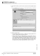
1. Right-click the I/O system and select the menu item "Assign device names" in the

context menu.

ð

The following window is displayed: 

19210163723

22870857/EN – 12/2016

Содержание MOVIMOT MM D Series

Страница 1: ... 22870857_1216 Drive Technology Drive Automation System Integration Services Manual Drive System for Decentralized Installation PROFINET IO Interfaces Field Distributors Edition 12 2016 22870857 EN ...

Страница 2: ...SEW EURODRIVE Driving the world ...

Страница 3: ...ignation of the PROFINET IO interfaces 17 4 3 Field distributor 18 4 4 Type designation of the PROFINET IO field distributors 23 5 Mechanical installation 28 5 1 Installation instructions 28 5 2 Tightening torques 29 5 3 Fieldbus interfaces MF MQ 31 5 4 Field distributor 34 6 Electrical installation 39 6 1 Installation planning taking EMC aspects into account 39 6 2 Installation instructions for f...

Страница 4: ...or writing the parameterization via dataset 47 127 10 Function 130 10 1 Meaning of the LED display 130 10 2 Performance configuration MFZ29 field distributor with 3 MOVIMOT drives 133 11 Supplementary field distributor startup information 134 11 1 MF Z 6 field distributor 134 11 2 MF MM Z 7 field distributor 135 11 3 MF MM Z 8 field distributor 137 11 4 MF MM Z 9 field distributor 139 11 5 MOVIMOT...

Страница 5: ...erfaces Field Distributors 5 15 Technical data 174 15 1 Technical data MFE52B PROFINET IO interface 174 15 2 Technical data for field distributors 176 16 Declaration of conformity 179 17 Address list 181 Index 192 22870857 EN 12 2016 ...

Страница 6: ...Z 3 with fieldbus interface 4 x I 2 x IO M12 PROFINET IO MFE52B Z23D Field distributor Z 6 with fieldbus interface 4 x I 2 x IO M12 PROFINET IO MFE52B Z26F AF0 Field distributor Z 7 with fieldbus interface 4 x I 2 x IO M12 PROFINET IO MFE52B MM Z27F Field distributor Z 8 with fieldbus interface 4 x I 2 x IO M12 PROFINET IO MFE52B MM Z28F AF0 Field distributor Z 9 with fieldbus interface 4 x I 2 x ...

Страница 7: ... 2 1 Meaning of signal words The following table shows the grading and meaning of the signal words for safety notes Signal word Meaning Consequences if disregarded DANGER Imminent hazard Severe or fatal injuries WARNING Possible dangerous situation Severe or fatal injuries CAUTION Possible dangerous situation Minor injuries NOTICE Possible damage to property Damage to the product or its envir onme...

Страница 8: ...cal voltage Warning of hot surfaces Warning of risk of crushing Warning of suspended load Warning of automatic restart 2 2 3 Structure of embedded safety notes Embedded safety notes are directly integrated into the instructions just before the de scription of the dangerous action This is the formal structure of an embedded safety note SIGNAL WORD Type and source of hazard Possible consequence s if...

Страница 9: ... characteristics and performance features SEW EURODRIVE as sumes no liability for injury to persons or damage to equipment or property resulting from non observance of these operating instructions In such cases SEW EURODRIVE assumes no liability for defects 2 5 Other applicable documentation You must also note the following documents AC Motor operating instructions MOVIMOT MM D operating instructi...

Страница 10: ...isassembly Waste disposal Make sure persons working on the product adhere to the following regulations re quirements documents and information National and regional safety and accident prevention regulations Warning and safety signs on the product All other relevant project planning documents installation and startup instructions wiring diagrams and schematics Do not assemble install or operate da...

Страница 11: ... product is intended for installation in electrical plants or machines In case of installation in electrical systems or machines startup of the product is pro hibited until it is determined that the machine meets the requirements stipulated in the local laws and directives For Europe Machinery Directive 2006 42 EC as well as the EMC Directive 2014 30 EU apply Observe EN 60204 1 Safety of machinery...

Страница 12: ...ntation 3 7 Installation assembly Ensure that the product is installed and cooled according to the regulations in the doc umentation Protect the product from excessive mechanical strain The product and its mounted components must not protrude into the path of persons or vehicles Ensure that com ponents are not deformed and that insulation spaces are maintained particularly dur ing transportation E...

Страница 13: ...able national accident prevention guidelines be fore you work on the product Perform electrical installation according to the pertinent regulations e g cable cross sections fusing protective conductor connection The documentation at hand con tains additional information Make sure that all required covers are installed correctly after electrical installation Make sure that preventive measures and p...

Страница 14: ...s at any connected cables and terminals This also applies even when the product is inhibited and the motor is at standstill Do not separate the connection to the product during operation This may result in dangerous electric arcs damaging the product If you disconnect the product from the voltage supply do not touch any live compon ents or power connections because capacitors might still be charge...

Страница 15: ...ckets for digital inputs outputs 2 Status LEDs of digital inputs outputs 3 X12 PROFINET IO connection port 2 4 X11 PROFINET IO connection port 1 5 Diagnostic interface below screw fitting 6 Diagnostics LEDs 4 1 2 Interface bottom side The following figure depicts the bottom side of the fieldbus interface 3 2 4 5 ON 1 2 3 4 S1 Ether ne tm od ul Sac hn r 18 24 13 79 Ser ienr 50 50 09 12 34 6 MFE52 A...

Страница 16: ...tion module The following figure shows the MFZ connection module 3 5 4 3 4 2 3 1 9007200390917003 1 Terminal strip X20 2 Isolated terminal block for 24 V through wiring NOTICE Do not use for shielding 3 M20 cable gland 4 M12 cable gland 5 Grounding terminal The scope of delivery includes 2 EMC cable glands 22870857 EN 12 2016 ...

Страница 17: ...ce MFP PROFIBUS MQP PROFIBUS with integrated minicontroller MFE PROFINET IO EtherNet IP or EtherCAT MFD DeviceNet MQD DeviceNet with integrated minicontroller 52 Connections 21 4 x I 2 x O connection via terminals 22 4 x I 2 x O connection via plug connector terminals 32 6 x I connection via plug connector terminals 52 4 x I 2 x I O connection via plug connector terminals for PROFINET IO 62 4 x I ...

Страница 18: ...36971 1 For DeviceNet Micro style connector M12 connector X11 2 2 x M20 x 1 5 3 2 x M25 x 1 5 4 2 x M16 x 1 5 2 EMC cable glands included in the delivery 5 Terminals for fieldbus connection X20 6 Terminals for 24 V connection X21 7 Terminals for power supply and PE connection X1 8 Connection PE equipotential bonding 9 Socket for connecting hybrid cable to MOVIMOT X9 22870857 EN 12 2016 ...

Страница 19: ... to MOVIMOT inverter X9 5 Maintenance switch with line protection triple lock color black red Only for MFZ26J design Optional integrated feedback for position of the mainten ance switch The feedback is evaluated at digital input DI0 see chapter Connection of field bus interface inputs outputs I ON I ON 0 OFF 0 OFF Ø 5 Ø 8 mm 6 Terminals for power supply and PE connection X1 7 Terminals for bus sen...

Страница 20: ...connector X11 3 Connection PE equipotential bonding 4 Hybrid cable connection connection to AC motor X9 5 Terminals for bus sensor actuator 24 V connection X20 6 Pluggable terminal Safety Power for 24 V MOVIMOT supply X40 7 Terminal block for 24 V through wiring X29 internal connection to 24 V on X20 8 MOVIMOT inverter 9 Connection to MOVIMOT inverter 10 Terminals for enabling the direction of rot...

Страница 21: ...aintenance switch triple lock color black red Only with MFPZ28J design Optional integrated feedback for position of the maintenance switch The feedback is evaluated at digital input DI0 see chapter Connection of field bus interface inputs outputs I ON I ON 0 OFF 0 OFF Ø 5 Ø 8 mm 5 MOVIMOT inverter 6 Terminals for bus sensor actuator 24 V connection X20 7 Pluggable terminal Safety Power for 24 V MO...

Страница 22: ... terminals X4_ 3 3 x M25 x 1 5 cable gland EMC cable glands supplied as an option 4 Motor control terminals X6_ 5 2 x M25 x 1 5 cable glands 6 2 x M20 x 1 5 cable glands 7 Equipotential bonding connection 8 Option maintenance switch triple lock color black red Only with MFZ29J design Feedback option for position of the maintenance switch I ON I ON 0 OFF 0 OFF Ø 5 Ø 8 mm 9 Terminals for L1 L3 line ...

Страница 23: ...ED IND CONT EQ 2D06 01 N2936 X2 X11 X3 X12 X13 X15 X14 X16 1 1 Nameplate 01 Only field distributors marked with the FS logo for functional safety may be installed in safety applications For field distributors marked with the FS logo the safety function must be described in the documentation 4 4 2 Type designation MF Z 3 The following table shows the type designation for MF Z 3 field distributors a...

Страница 24: ...le MFE 52B Fieldbus interface MFP MQP PROFIBUS MFE PROFINET IO EtherNet IP or EtherCAT MFD MQD DeviceNet Z26 Connection module Z26 for PROFIBUS PROFINET IO EtherNet IP and EtherCAT Z36 For DeviceNet F Variant AF0 Connection technology AF0 Metric cable entry AF1 With micro style connector M12 connector for DeviceNet AF2 M12 plug connector for PROFIBUS AF3 M12 plug connector for PROFIBUS M12 plug co...

Страница 25: ...ion for MF MM Z 7 field distributors as an example MFE 52B Fieldbus interface MFP MQP PROFIBUS MFE PROFINET IO EtherNet IP or EtherCAT MFD MQD DeviceNet MM15D 503 00 MOVIMOT inverter Z27 Connection module Z27 for PROFIBUS PROFINET IO EtherNet IP and EtherCAT Z37 For DeviceNet F Variant 0 Connection type 0 W 1 m BW1 Braking resistor option BW1 Braking resistor for MOVIMOT MM03 MM15 22870857 EN 12 2...

Страница 26: ...rCAT MFD MQD DeviceNet MM15D 503 00 MOVIMOT inverter Z28 Connection module Z28 for PROFIBUS PROFINET IO EtherNet IP and EtherCAT Z38 For DeviceNet F Variant 0 Connection type 0 W 1 m BW1 Braking resistor option BW1 Braking resistor for MOVIMOT MM03 MM15 BW2 Braking resistor for MOVIMOT MM22 MM40 AF0 Connection technology AF0 Metric cable entry AF1 With micro style connector M12 connector for Devic...

Страница 27: ...FINET IO MM15D 503 00 MOVIMOT inverter No designation without inverter MM D MOVIMOT inverter Z29 Connection module Z29 for PROFINET IO F Variant N without maintenance switch F with maintenance switch J with maintenance switch and feedback 0 Connection type 0 W 1 m BW1 Braking resistor option BW1 Braking resistor for MOVIMOT MM03 MM15 3 Number of MOVIMOT inverters 0 without inverter 1 1 MOVIMOT inv...

Страница 28: ...ws and suitable washers for attaching the MFZ 3 field distributor Tighten screws with a torque wrench permitted tightening torque 2 8 3 1 Nm Use M6 screws and suitable washers for installing MFZ 6 MFZ 7 MFZ 8 or MFZ 9 field distributors Tighten screws with torque wrench permitted tightening torque 3 1 3 5 Nm 5 1 2 Installation in damp locations or in the open Observe the following notes for mounti...

Страница 29: ...1 MOVIMOT inverter 9007200393241611 Tighten the screws for fastening MOVIMOT using 3 0 Nm in diametrically opposite sequence 5 2 2 Fieldbus interface connection box cover 9007200393245323 Tighten the screws on the fieldbus interfaces or connection box cover using 2 5 Nm in diametrically opposite sequence 22870857 EN 12 2016 ...

Страница 30: ...ighten EMC cable glands supplied by SEW EURODRIVE using the following torque ratings Screw fitting Tightening torque M12 x 1 5 2 5 Nm 3 5 Nm M16 x 1 5 3 0 Nm 4 0 Nm M20 x 1 5 3 5 Nm 5 0 Nm M25 x 1 5 4 0 Nm 5 5 Nm The cable retention in the cable gland must be able to withstand the following removal force Cable with outer diameter 10 mm 160 N Cable with outer diameter 10 mm 100 N 5 2 5 Motor cable ...

Страница 31: ...ed as follows Installation on MOVIMOT connection box Installation in the field mounting close to the motor 5 3 1 Installation on MOVIMOT connection box 1 Remove the knock outs at the MFZ lower section from the inside as shown in the following figure MFZ 1 1138656139 ð If necessary deburr the break lines that occur after the knock outs 1 have been removed 22870857 EN 12 2016 ...

Страница 32: ...Fieldbus interfaces MF MQ Manual PROFINET IO Interfaces Field Distributors 32 2 Mount the fieldbus interface to the MOVIMOT connection box according to the following figure MF MQ 3 0 3 5 Nm 18014399648145931 22870857 EN 12 2016 ...

Страница 33: ...T IO Interfaces Field Distributors 33 5 3 2 Installation in the field The following figure shows the installation of an MF MQ fieldbus interface close to the motor 82 5 mm 102 mm 51 mm M4 M4 MFZ MF MQ MF MQ 1 1138749323 1 Length of screws min 40 mm 22870857 EN 12 2016 ...

Страница 34: ...F Z 3 MQ Z 3 field distributors The following figure shows the mounting dimensions for Z 3 field distributors 50 mm 100 mm M5 M5 175 mm 9007200393500299 5 4 2 Installation of MF Z 6 MQ Z 6 field distributors The following figure shows the mounting dimensions for Z 6 field distributors M6 M6 365 mm 180 mm 18014399648277003 22870857 EN 12 2016 ...

Страница 35: ...stributors The following figure shows the mounting dimensions for Z 7 field distributors 59 5 mm 253 7 mm M6 M6 18014399648313483 5 4 4 Installation of MF MM Z 8 MQ MM Z 8 field distributors Size 1 The following figure shows the mounting dimensions for Z 8 field distributors Size 1 290 mm 200 mm 270 mm M6 M6 18014399648325131 22870857 EN 12 2016 ...

Страница 36: ...NET IO Interfaces Field Distributors 36 5 4 5 Installation of MF MM Z 8 MQ MM Z 8 field distributors Size 2 The following figure shows the mounting dimensions for Z 8 field distributors Size 2 350 mm 205 mm 290 mm M6 M6 18014399648338187 22870857 EN 12 2016 ...

Страница 37: ...Manual PROFINET IO Interfaces Field Distributors 37 5 4 6 Installation of MF MM Z 9 field distributors The following figure shows the mounting dimensions for Z 9 field distributors 145 mm 282 mm 60 mm 507 mm M6 M6 18223713419 22870857 EN 12 2016 ...

Страница 38: ... Electric shock due to missing cover Severe or fatal injuries If you install only 1 or 2 MOVIMOT inverters at the field distributor you have to cover all free slots with the delivered covers Make sure that there are no open slots NOTICE Loss of the ensured degree of protection due to impermissible installation If you connect only 1 MOVIMOT inverter or only the fieldbus interface to the field distr...

Страница 39: ... notes in the following chapters in particular 6 1 1 Equipotential bonding Low resistance and HF capable equipotential bonding must be provided independent of the PE connection see also VDE 0113 or VDE 0100 part 540 Establish a connection over a wide surface area between the field distributor and the sys tem untreated unpainted uncoated mount ing surface 2 1 3 17948651787 1 Conductive connection o...

Страница 40: ...on EMC in Drive Engineering 6 1 6 Example for connection of the MF MQ fieldbus interface and MOVIMOT If the MF MQ fieldbus interface and MOVIMOT are installed separately the RS485 connection must be implemented as follows Carrying the DC 24 V supply Use shielded cables Connect the shield to the housing of both devices using EMC cable glands Twist the conductors in pairs as shown in the following f...

Страница 41: ...ne for rated power see MOVIMOT operating instructions Technical data chapter Install fuses at the beginning of the power supply cables behind the supply bus junction The following fuses are permitted Fuses in utilization category gG Power circuit breakers with characteristic B or C Motor circuit breaker Size the fuses according to the cable cross section SEW EURODRIVE recommends using earth leakag...

Страница 42: ...nect only single wire conductors or flexible conductors with conductor end sleeves DIN 46228 material E CU with or without plastic collars For double assignment Connect only flexible conductors with conductor end sleeve DIN 46228 1 material E CU without plastic collar Permitted length of the conductor end sleeve at least 8 mm Control terminals Adhere to the permitted cable cross sections for insta...

Страница 43: ... 6 2 5 Line contactor NOTICE Damage to the MOVIMOT inverter when using the line contractor K11 for jog mode Damage to the MOVIMOT inverter Do not use the K11 line contactor see wiring diagram for jog mode but only for switching the inverter on and off For jog mode use the commands CW Stop or CCW Stop Observe a minimum switch off time of 2 s for the input contactor K11 Only use a contactor of utili...

Страница 44: ...ked cable lug Permitted for all cross sections Assembly with solid connecting wire Permitted for cross section up to max 2 5 mm2 1 M5 2 5 mm M5 1 Forked cable lug suitable for M5 PE screws Earth leakage currents of 3 5 mA can occur during normal operation To meet the requirements of EN 61800 5 1 observe the following notes The protective earth PE connection must meet the requirements for plants wi...

Страница 45: ...h the DC 24 V supply voltage in the MFZ 1 module terminal box There are 2 M4 x 12 studs in the connection area of the DC 24 V supply The studs can be used for looping the DC 24 V supply voltage 1140831499 The terminal studs have a current carrying capacity of 16 A The permitted tightening torque for the hex nuts of the terminal studs is 1 2 Nm 20 22870857 EN 12 2016 ...

Страница 46: ...cs and sensors studs jumpered with terminal X20 13 The plug in terminal X40 Safety Power is intended for the external DC 24 V supply of the MOVIMOT inverter using a safety relay This setup allows for the operation of a MOVIMOT drive with FS marking in safety applications For detailed information refer to the MOVIMOT MM D Functional Safety manual Terminal assignment No Name Function X40 1 24 V 24 V...

Страница 47: ...ovide branch circuit protection Branch circuit protection must be provided in accordance with the National Electrical Code and any additional local codes For maximum branch circuit protection see table below Series non semiconductor fuses inverse time circuit breaker MOVIMOT MM D 250 V 500 V minimum 25 A maximum 250 V 500 V minimum 25 A maximum Motor overload protection MOVIMOT MM D is provided wi...

Страница 48: ...separate MF Z21 MOVIMOT installation Connect the shield of the RS485 cable using the EMC metal cable gland on MFZ and the MOVIMOT housing 2 Ensure equipotential bonding between all bus stations 3 Assignment of terminals 19 36 see chapter Connection of the inputs outputs of the MFE52 fieldbus interface 2 62 Terminal assignment No Name Direction Function X20 1 10 Res Reserved 11 24 V Input 24 V volt...

Страница 49: ...0 Potential level 0 1 Potential level 1 2 Potential level 2 Terminal assignment No Name Direction Function X20 1 10 Res Reserved X21 1 24 V Input 24 V voltage supply for module electronics DI0 DI3 sensors and MOVIMOT 2 24 V Output 24 V voltage supply for module electronics DI0 DI3 sensors and MOVIMOT jumpered with terminal X21 1 3 GND 0V24 reference potential for module electronics sensors DI0 DI3...

Страница 50: ...es res res res res res res 9007202581246987 0 Potential level 0 1 Potential level 1 2 Potential level 2 Terminal assignment No Name Direction Function X20 1 10 Res Reserved X21 1 24 V Input 24 V voltage supply for module electronics sensors and MOVIMOT 2 24 V Output 24 V voltage supply jumpered with terminal X21 1 3 GND 0V24 reference potential for module electronics sensors and MOVIMOT 4 GND 0V24...

Страница 51: ...s res res 9007202581330955 0 Potential level 0 1 Potential level 1 2 Potential level 2 1 Assignment of terminals 19 36 see chapter Connection of the inputs outputs of the MFE52 fieldbus interface 2 62 Terminal assignment No Name Direction Function X20 1 10 Res Reserved 11 24 V Input 24 V voltage supply for module electronics and sensors DI0 DI3 12 24 V Output 24 V voltage supply for module electro...

Страница 52: ...s res res 9007202581354763 0 Potential level 0 1 Potential level 1 2 Potential level 2 1 Assignment of terminals 19 36 see chapter Connection of the inputs outputs of the MFE52 fieldbus interface 2 62 Terminal assignment No Name Direction Function X20 1 10 Res Reserved 11 24 V Input 24 V voltage supply for module electronics and sensors 12 24 V Output 24 V voltage supply jumpered with terminal X20...

Страница 53: ...MM2 PE 13 PE 10 PE 7 MM3 18210880779 1 X1 Supply system terminals 2 X20 24 V distributor terminals 3 X21 24 V supply terminals 24 V power bus 4 MM1 Slot for MOVIMOT inverter 1 with RS485 address 1 5 MM2 Slot for MOVIMOT inverter 2 with RS485 address 2 6 MM3 Slot for MOVIMOT inverter 3 with RS485 address 3 7 PE MM3 Motor 3 PE connection 8 X4_3 Motor 3 power terminals U V W brake 9 X6_3 Motor 3 cont...

Страница 54: ...3 1 Potential level 1 2 Potential level 2 Terminal assignment 24 V supply terminals No Name Direction Function X21 1 24V_C Input 24 V voltage supply for module electronics sensors and actuators 2 24V_C Output 24 V voltage supply for module electronics sensors and actuators jumpered with terminal X21 1 3 0V24_C Input 0V24 reference potential for module electronics sensors and actuators 4 0V24_C Out...

Страница 55: ...MOVIMOT inverters jumpered with terminal X21 7 5 24V_C_S Output Feedback signal of the maintenance switch 24V_C_S 24 V maintenance switch is switched on 6 DI0 Input Switching input DI0 e g for feedback of the maintenance switch DI0 1 maintenance switch is switched on 2 59 7 DO0 DI4 Input out put Digital input output for manual enable signal connection variant rapid start rapid stop 2 60 8 K1a Inpu...

Страница 56: ...al level 2 Terminal assignment 24 V supply terminals No Name Direction Function X21 1 24V_C Input 24 V voltage supply for module electronics sensors and actuators 2 24V_C Output 24 V voltage supply for module electronics sensors and actuators jumpered with terminal X21 1 3 0V24_C Input 0V24 reference potential for module electronics sensors and actuators 4 0V24_C Output 0V24 reference potential fo...

Страница 57: ...MOVIMOT inverters jumpered with terminal X21 7 5 24V_C_S Output Feedback signal of the maintenance switch 24V_C_S 24 V maintenance switch is switched on 6 DI0 Input Switching input DI0 e g for feedback of the maintenance switch DI0 1 maintenance switch is switched on 2 59 7 DO0 DI4 Input out put Digital input output for manual enable signal connection variant rapid start rapid stop 2 60 8 K1a Inpu...

Страница 58: ...1b K1a HT0 DI0 DO0 DI4 X6_1 MM1 MM2 MM3 X1 L2 L2 L3 L3 L1 L1 1 2 18196627211 1 The cables labeled with are already wired at the factory 2 The cables labeled with still have to be wired for this connection variant Function With this additional connection the digital input DI4 shows if any of the MOVIMOT in verters is ready for operation DI4 0 No MOVIMOT inverter is ready for operation e g 24V_P is ...

Страница 59: ...tory Function With this additional connection the field distributor delivers the status of the mainten ance switch to the higher level controller Maintenance switch on digital input DI0 1 Maintenance switch off digital input DI0 0 The STO Safe Torque Off safety function of the MOVIMOT drives is possible Depending on the configuration the following is available 3 digital inputs DI1 DI3 and 2 digita...

Страница 60: ...th are already wired at the factory 2 The cables labeled with still have to be wired for this connection variant Requirement All MOVIMOT inverters of the field distributor have to be enabled in the process data 2 146 Function With this additional connection you can simultaneously start or stop all connected MOVIMOT drives If you set the digital output DO0 1 the drives start If you set the digital ...

Страница 61: ...osed ready for operation 7 TH Input TH connection bimetallic thermostat in the motor 8 TH Input TH connection bimetallic thermostat in the motor 9 L Input Direction enable CCW 10 L Input Direction enable CCW 11 R Input Direction enable CW 12 R Input Direction enable CW 1 X6_1 connections for motor 1 2 X6_2 connections for motor 2 3 X6_3 connections for motor 3 6 6 4 X4_1 X4_2 X4_3 motor 1 3 power ...

Страница 62: ... GND VO24 DI3 GND VO24 DIO4 GND2 DIO5 GND2 GND2 1 2 X20 V2I24 9007202583107851 1 Potential level 1 2 Potential level 2 Terminal assignment No Name Direction Function X20 19 DI0 Input Sensor DI0 switching signal1 20 GND 0V24 reference potential for sensor DI0 21 V024 Output 24 V voltage supply for sensor DI01 22 DI1 Input Sensor DI1 switching signal 23 GND 0V24 reference potential for sensor DI1 24...

Страница 63: ...ensor DI5 switching signal Output Actuator DO1 switching signal 34 GND2 0V24 reference potential for sensor DI5 0V24 reference potential for actuator DO1 35 V2I24 Input 24 V voltage supply for actuators only for MFZ 6 MFZ 7 and MFZ 8 jumpered with terminal 15 or 16 36 GND2 0V24 reference potential for actuators DO0 and DO1 or sensors DI4 and DI5 only for MFZ 6 MFZ 7 and MFZ 8 jumpered with termina...

Страница 64: ...o the fieldbus interface Seal all unused M12 connections with screw plugs Connect sensors actuators using either M12 sockets or terminals When using outputs Connect 24 V to V2I24 GND2 terminals Connect dual channel sensors actuators to DI0 DI2 and DI4 DO0 DI1 DI3 and DI5 DO1 can no longer be used DIO DI1 GND GND DI1 24 V V024 24 V V024 DI1 1 2 3 5 4 1 2 3 5 4 DI0 DI2 DI3 GND GND DI3 24 V V024 24 V...

Страница 65: ...g either M12 sockets or terminals When using outputs Connect 24 V to V2I24 GND2 terminals The following sensors actuators can be connected 4 single channel sensors and 2 single channel actuators or 6 single channel sensors The second channel is not connected when dual channel sensors actuators are used DIO DI1 GND GND n c 24 V V024 24 V V024 DI1 1 2 3 5 4 1 2 3 5 4 DI0 DI2 DI3 GND GND n c 24 V V02...

Страница 66: ...1 link act2 M F E 5 2 A E t h e r n e t SYS F 2 1 9007202600365067 1 X11 PROFINET IO connection port 1 2 X12 PROFINET IO connection port 2 The following table shows the pin assignment of the PROFINET IO ports X11 and X12 Function PROFINET IO interface Connection type M12 4 pole female D coded Wiring diagram 1 2 3 4 3545032843 Assignment No Name Function 1 TX Transmit line 2 RX Receive line 3 TX Tr...

Страница 67: ...e devices a telegram has to pass through the higher the tele gram runtime is For a telegram length of 64 bytes by approximately 10 µs at 100 Mbit s For a telegram length of 1500 bytes by approximately 130 µs at 100 Mbit s Auto crossing The two ports leading out of the Ethernet switch have auto crossing functionality This means that they can use both patch and cross over cables to connect to the ne...

Страница 68: ...cat egory 5 class D according to IEC 11801 edition 2 0 The following measures ensure the best possible EMC properties Manually tighten the mounting screws on the connectors modules and equipotential bonding conductors Use only connectors with a metal housing or a metalized housing Route signal and bus cables in separate cable ducts Do not route them parallel to power cables motor leads Use metalli...

Страница 69: ... assignment MOVIMOT terminal Wire color hybrid cable designation L1 Black L1 L2 Black L2 L3 Black L3 24 V Red 24 V White 0 V RS Orange RS RS Green RS PE terminal Green yellow shield end Note the enabled direction of rotation Check to see if requested direction of rotation has been enabled 24V L R Both directions of rotation are enabled L R 24V Drive is inhibited or is being brought to a standstill...

Страница 70: ... 7 MFZ 8 9007200402006667 The following table shows the terminal assignment of the hybrid cable in the motor ter minal box Terminal assignment Motor terminal Wire color hybrid cable designation U1 Black U1 V1 Black V1 W1 Black W1 4a Red 13 3a White 14 5a Blue 15 1a Black 1 2a Black 2 PE terminal Green yellow shield end inner shield INFORMATION Attach the outer shield of the cable to the housing of...

Страница 71: ... Motor ter minal Wire color hybrid cable designation Field distributor terminal Motor 1 connection Motor 2 connection Motor 3 connection U1 Black U1 X4_1 4 X4_2 4 X4_3 4 V1 Black V1 X4_1 5 X4_2 5 X4_3 5 W1 Black W1 X4_1 6 X4_2 6 X4_3 6 4a Red 13 X4_1 1 X4_2 1 X4_3 1 3a White 14 X4_1 2 X4_2 2 X4_3 2 5a Blue 15 X4_1 3 X4_2 3 X4_3 3 1a Black 1 X6_1 3 X6_2 3 X6_3 3 2a Black 2 X6_1 7 X6_2 7 X6_3 7 PE t...

Страница 72: ...ug before plugging in the connector into the diagnostic interface WARNING Danger of burns from the hot surfaces of the MOVIMOT drive in particular the heat sink Severe injuries Wait for the MOVIMOT drive to cool down sufficiently before touching it The diagnostic interface is connected to a commercially available PC Laptop via the USB11A interface adapter with USB port part number 08248311 MF MQ R...

Страница 73: ...ith MFZ 7 MFZ 8 MFZ 9 Disconnect all plug connectors of the motor connection hybrid cable from the field distributor Check the insulation of the wiring in accordance with applicable national stand ards Check the grounding Check the insulation between the supply system cable and the DC 24 V cable Check the insulation between supply system cable and communication cable Check the polarity of the DC 2...

Страница 74: ...ute WARNING Danger of burns due to hot surfaces of the device e g the heat sink Serious injuries Do not touch the device until it has cooled down sufficiently WARNING Device malfunction due to incorrect device setting Severe or fatal injuries The installation may only be carried out by qualified personnel Only use settings that are suitable for operation NOTICE Danger due to arcing Damage to elect...

Страница 75: ...ives to the MFZ 1 connection module If more than 1 MOVIMOT drive is connec ted to the MFZ 1 connection module a drive that is not enabled may start up during operation Severe or fatal injuries Make sure that only 1 MOVIMOT drive is connected to the MFZ 1 connection module Use the MFZ29 field distributor for controlling several drives WARNING Uncontrolled enable of an unexpected drive due to incorr...

Страница 76: ... is difficult to handle for larger networks This is why freely assignable IP ad dresses are used 7 2 3 IP address The IP address is a 32 bit value that uniquely identifies a node in the network An IP address is represented by 4 decimal numbers separated by decimal points Example 192 168 10 4 Each decimal number stands for one byte 8 bits of the address and can also be represented using binary code...

Страница 77: ...n also be represented using binary code following table Byte 1 Byte 2 Byte 3 Byte 4 11111111 11111111 11111111 10000000 If you compare the IP addresses with the subnet masks you see that in the binary representation of the subnet mask all ones determine the network address and all the zeros determine the node address see following table Byte 1 Byte 2 Byte 3 Byte 4 IP address decimal 192 168 10 129...

Страница 78: ...68 10 1 The standard gateway establishes a connection to other networks In this way a net work node that wants to address another node can use logic AND operation with the IP address and the subnet mask to decide whether the desired node is located in the same network If this is not the case the node addresses the standard gateway router which must be part of the actual network The standard gatewa...

Страница 79: ...y voltage including DC 24 V off and on again 7 3 3 SEW Address Editor The SEW Address Editor allows you to access the IP settings of the fieldbus interface without the Ethernet settings of the PC and the fieldbus interface having to match The IP settings of all SEW EURODRIVE devices can be defined and displayed in the local subnetwork using the Address Editor in MOVITOOLS MotionStudio For more inf...

Страница 80: ...erter and the fieldbus interface are installed correctly 3 WARNING Uncontrolled enable of an unexpected drive due to incorrect field bus interface at the MFZ29 field distributor Severe or fatal injuries Make sure the MFE52B or MFE52G fieldbus interface is installed on the MFZ29 field distributor 4 WARNING Uncontrolled enable of an unexpected drive due to incorrect ad dress setting Severe or fatal ...

Страница 81: ...t setting 0 1 2 3 4 5 6 7 8 9 10 Minimum frequency fmin Hz 2 5 7 10 12 15 20 25 30 35 40 9 If the ramp time is not specified via fieldbus 2 PD set the ramp time at the t1 switches of all MOVIMOT inverters ð The ramp time is based on a setpoint step change of 1500 min 1 50 Hz 3 4 5 6 7 8 Function Setting Detent setting 0 1 2 3 4 5 6 7 8 9 10 Ramp time t1 s 0 1 0 2 0 3 0 5 0 7 1 2 3 5 7 10 10 Check ...

Страница 82: ...he field distributor and tighten with screws Observe the notes on installation of the MOVIMOT inverters at the MFZ29 field distributor 2 37 13 WARNING Uncontrolled enable of an unexpected drive by swapping the MOVIMOT inverters only for MFZ29 Severe or fatal injuries Install the MOVIMOT inverters of the MFZ29 field distributor based on the set RS485 address according to the following figure 14 15 ...

Страница 83: ...when the MS LED at the MFE fieldbus interface lights up green ð The red SYS F LED is not lit 16 Configure the MFE fieldbus interface at the PROFINET IO controller In conjunction with PROFINET IO no further settings are required on the drives The PROFINET IO is configured entirely using software tools For more information about configuration refer to chapter PROFINET IO configuration in the manual ...

Страница 84: ...18867508875 ð This sets the address parameters to the following default values IP address 192 168 10 4 Subnet mask 255 255 255 0 Gateway 0 0 0 0 4 Re install the MFE Ethernet interface on the field distributor 5 Turn on the 24 V voltage supply and wait until the MS LED lights up green 6 Remove the MFE Ethernet interface from the field distributor 7 At the MFE Ethernet interface set DIP switch S1 2...

Страница 85: ... controllers in one PROFINET IO system IO device All field units on PROFINET IO that are controlled by an IO controller are called IO devices e g I Os drives valve terminals etc IO devices are comparable with PROFIBUS DP slave nodes The MFE PROFINET IO interface is a PROFINET IO device IO supervisor Programming devices PC with corresponding engineering diagnostic tools are called IO supervisors IO...

Страница 86: ...enable logical modularization e g for a drive system see following figure Ethernet Port 3548829835 A single drive axis is represented as a module under PROFINET IO Several submod ules can be plugged into this module The submodules define the process data inter face for the IO controller or data traffic partner They have provider or consumer qual ity The model provides the option to plug several mo...

Страница 87: ...n unexpected drive due to installation of an invalid GSDML file If you install an invalid GSDML file during configuration a drive that is not en abled may start up during operation Severe or fatal injuries For configuring the MFZ29 field distributor install the current GSDML file GSDML V2 25 SEW MFE52A jjjjmmtt hhmmss xml and select the MFE V1 2 3MM entry The latest GSDML file version is also avai...

Страница 88: ...ur control type and add the required modules The following modules make sense ð OB82 module This module makes sure that the controller does not trigger STOP in the event of so called diagnostic alarms ð OB86 module This module indicates the failure of decentralized peripherals ð OB122 module This module is called if the controller cannot access the data of a node of the decentralized periphery Thi...

Страница 89: ...M entry on the PROFINET IO system 2 Right click on the system and select the menu item Assign device names from the context menu Enter the PROFINET IO station name ð This name must later correspond to the PROFINET IO device name set in the MFE PROFINET IO interface 19209922955 3 Mark the symbol of the MFE PROFINET IO interface 4 Switch to the Device view tab 5 Delete the slot entries that are no l...

Страница 90: ...ion example 19209928843 ð An empty module must be assigned to unused slots 8 Save the configuration 9 Expand your application program by the data exchange with the MFE PROFINET IO interfaces 10 Save the project and load it into the PROFINET IO controller Now the BUS F LED of the MFE PROFINET IO interface should go out If not check the PROFINET wiring the LED link act and the configuration especial...

Страница 91: ...er when the node is configured and also set using the configuration software on the PROFINET IO device During startup the IO controller identifies the device based on the device name and transfers the corresponding IP address parameters The settings directly at the slave are thus no longer necessary The following example with the TIA Portal configuration software describes the gen eral procedure ü...

Страница 92: ...e name is set at the factory to a default name including the MAC ID for example PnetDeviceName 00 0F 69 XX XX XX ð Several SEW nodes can be differentiated by the displayed MAC addresses The MAC address is affixed to the MFE PROFINET IO interface You can loc ate the selected MFE PROFINET IO interface using the Flash button which lets the BUS F LED of the selected MFE PROFINET IO interface flash in ...

Страница 93: ... Distributors 93 4 Click the Assign name button ð The following window is displayed 19210194187 ð If the device name has been assigned correctly a check mark appears next to the PROFINET device name see the following figure 19210199051 5 Close the Assign PROFINET device name window 22870857 EN 12 2016 ...

Страница 94: ... MFE PROFINET IO interface Slot Assignment DP ID Plug in modules 1 Reserved Slot not used 2 MFE status Slot not used MFE status 3 Digital inputs Slot not used 4 6 DI 4 Digital outputs Slot not used 2 DO 5 MOVIMOT 1 Slot not used MOVIMOT 2PD MOVIMOT 3PD 6 MOVIMOT 2 only for MFZ29 field distributor Slot not used MOVIMOT 2PD MOVIMOT 3PD 7 MOVIMOT 3 only for MFZ29 field distributor Slot not used MOVIM...

Страница 95: ...Slot not used 2 MFE status MFE status_1 3 Digital inputs 4 6 DI_1 4 Digital outputs 2 DO_1 5 MOVIMOT 1 MOVIMOT 3PD_1 6 MOVIMOT 2 MOVIMOT 3PD_2 7 MOVIMOT 3 MOVIMOT 3PD_3 6 DI The following table shows a configuration with 6 inputs Slot Assignment Plug in module 1 Reserved Slot not used 2 MFE status MFE status_1 3 Digital inputs 4 6 DI_1 4 Digital outputs Slot not used 5 MOVIMOT 1 MOVIMOT 3PD 1 6 MO...

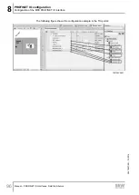
Страница 96: ...configuration Configuration of the MFE PROFINET IO interface Manual PROFINET IO Interfaces Field Distributors 96 The following figure shows the configuration example in the TIA portal 19210935691 22870857 EN 12 2016 ...

Страница 97: ...O interface supports diagnostic alarms in the event of a device fault These diagnostic alarms are deactivated by default Proceed as follows to switch on the alarms in the TIA Portal ü Make sure that the Device view tab is open 1 Select a slot 2 Switch to the Properties General tab 3 Select the menu item Module parameters 4 In Enable diagnosis alarms set the alarms to On 19210941067 22870857 EN 12 ...

Страница 98: ...ü Make sure that the Device view tab is open 1 Click the Go online icon to switch to the Online communication mode 2 Right click the icon of the SEW PROFINET connection and select the menu item Online and diagnostics in the context menu ð The following window is displayed 19211141003 3 Select the menu item Diagnostic status ð The window on the right shows the current diagnostic status INFORMATION ...

Страница 99: ...ct device type or defined the configuration incor rectly Perform the following steps 1 Delete the configuration of the MFE fieldbus interface from PROFINET 2 Configure the MFE fieldbus interface again this time choosing the correct device designation MFE V1 0 with topology detection or MFE V1 0 alt without topo logy detection 2 87 3 Assign the address ranges for your control system 4 Load the proj...

Страница 100: ... for configuration PDEV is a model for the Ethernet interface and can be found in slot 0 in the configuration with an Ethernet interface subslot and one subslot for each Ethernet port The Ethernet ports made visible in this way can be connected to the configuration tool The result is an image of the desired Ethernet routing for the plant This image is stored in the PROFINET IO controller To determ...

Страница 101: ...OFINET IO devices to the PROFINET IO network from the hardware catalog as usual ð All new SIEMENS CPUs support topology detection However you may have to activate topology detection in the Device view Properties General tab 19211500939 ð The hardware catalog contains several entries for each SEW interface marked as different versions An entry marked with ALT does not support the topology detection...

Страница 102: ...s and detect faulty connections to ports Refer to the online help for a detailed description and important additional information e g the color code of the comparison results Click Help to open the online help in the open topology editor Specifying the topology Proceed as follows to specify the topology of nodes in a PROFINET IO network 1 Switch to the Topology view tab 19212012683 2 Click the Com...

Страница 103: ...figuration PROFINET IO configuration with topology detection Manual PROFINET IO Interfaces Field Distributors 103 Repeat the procedure until all ports in the Status list are marked green 19212101003 22870857 EN 12 2016 ...

Страница 104: ... as follows 1 Switch to the Topology view tab 2 Click the Compare offline online button 19212110347 ð If the topology is already configured a note appears that there is a difference between online and offline mode 19212114315 ð If you switch to online mode failures are displayed as red lines 19212117259 INFORMATION If you use a switch you have to integrate the switch into the network as a PROFINET...

Страница 105: ... setup You can use patch or cross cables You can set a port to 100 Mbit s full duplex Observe the following for this setup This setting must also be made for the port of the neighboring device otherwise this neighboring port would work with 100 Mbit s half duplex If auto crossover is deactivated you have to use cross cables Proceed as follows to set a port to 100 Mbit s full duplex 1 Go to the Dev...

Страница 106: ...cs alarms The Network view shows the connection errors in form of a red cross 1 1 19272451595 Possible causes Ethernet ports swapped Incorrectly set port properties Devices cannot be addressed Proceed as follows to display information about an error 1 Select the device or the respective slot 2 Right click and select Module status from the context menu ð A window is displayed 3 Select the Communica...

Страница 107: ...ority of the process data exchange PO PROFINET Controller PI Read Write Record SEW PROFINET Device 9007200916805643 The user data transported via an acyclic PROFINET service is grouped in a data set Each dataset is clearly addressed by the following characteristics API Slot number Subslot number Index The structure of data set 47 is used for the parameter exchange with SEW EURODRIVE PROFINET devic...

Страница 108: ...rite Record services all have the same communication characteristics The devices are basically controlled via a PROFINET controller with cyclic process data Addition ally this controller usually a PLC can set the parameters for the SEW EURODRIVE PROFINET device via Read Record and Write Record Drive System Read Write Record PROFINET Cyclic IN Out Parameter Buffer 1 Parameter Buffer Process Data PD...

Страница 109: ...RITE PROFIdrive Parameter Channel DS47 SEW MOVILINK 9007200917532939 The following MOVILINK services are supported 8 byte MOVILINK parameter channel with all the services supported by the SEW device such as READ parameter WRITE parameter WRITE parameter volatile etc The following PROFIdrive services are supported Reading request parameter individual parameters of type double word Writing change pa...

Страница 110: ...m 0x60 Read default 0x80 Read attribute 0x90 Read EEPROM 0xA0 0xF0 reserved SEW data transport 0x10 value No of ele ments Unsigned8 0x00 for parameters that are not indexed 0x01 0x75 Quantity 1 117 Parameter Number Unsigned16 0x0000 0xFFFF MOVILINK parameter index Subindex Unsigned16 0x0000 SEW always 0 Format Unsigned8 0x43 double word 0x44 error No of Values Unsigned8 0x00 0xEA Quantity 0 234 Er...

Страница 111: ...rameterization response The SEW device sends a positive response READ response The user data now contains the parameter setting response of the parameter setting request that was previously sent with Write request see following figure This mechanism applies to a PROFINET controller The following figure shows the telegram sequence for the parameter access via READ WRITE RECORD Controller PROFINET S...

Страница 112: ... device has concluded the parameter access in the device This means that the response data from the SEW device is not yet available In this state the SEW device delays the response to the Read Record Request Send Write request with parameter data Send Read requset Check Write response Write response negative Write response positive Parameter transmission canceled with ERROR yes no Parameter transm...

Страница 113: ...NET Axis 0 PROFINET IO Controller Read Write Record SEW PROFINET Device 3549138059 Axis 0 MFE fieldbus interface 9 3 5 MOVILINK parameter requests The MOVILINK parameter channel of the SEW inverter is directly mapped in the structure of data set 47 The Request ID 0x40 SEW MOVILINK service is used to exchange MOVILINK parameter setting requests Parameter access with MOVILINK services usually takes ...

Страница 114: ... version is returned as an example Service READ re quest Description API 0 Fixed setting 0 Slot_Number 0 Random is not evaluated Subslot_Num ber 1 Fixed setting 1 Index 47 Index of the dataset for the parameter request con stant index 47 Length 10 Maximum length of response buffer in the master Byte Field Value Description 0 Response reference 0x01 Mirrored reference number from the para meter set...

Страница 115: ...ual reference number for the parameter setting request is mirrored in the parameter response 1 Request ID 0x40 SEW MOVILINK service 2 Axis 0x00 Axis number of the MFE fieldbus inter face 3 No of parameters 0x01 1 parameter 4 Attributes 0x10 MOVILINK service READ parameter 5 No of elements 0x00 0 access to direct value no subele ment 6 7 Parameter Number 0x206C MOVILINK index 8300 Firmware version ...

Страница 116: ...n 0 Request reference 0x01 Individual reference number for the para meter setting order is reflected in the para meter response 1 Request ID 0x40 SEW MOVILINK service 2 Axis 0x02 Mirrored axis number of the MOVIMOT drive Downward compatible routing via DS47 If DIP switch S1 1 OFF the system transfers the DS47 request with the axis address 2 to the RS485 address 254 of the MOVIMOT Routing to 3 MOVI...

Страница 117: ...iption API 0 Fixed setting 0 Slot_Number 0 Random is not evaluated Subslot_Num ber 1 Fixed setting 1 Index 47 Index of the dataset for the parameter request con stant index 47 Length 240 Maximum length of response buffer in the master Positive response to WRITE parameter volatile Service READ re sponse Description API 0 Fixed setting 0 Slot_Number 0 Random is not evaluated Subslot_Num ber 1 Fixed ...

Страница 118: ...ber 0 Random is not evaluated Subslot_Num ber 1 Fixed setting 1 Index 47 Index of the dataset for the parameter request con stant index 47 Length 8 8 byte user data in response buffer Byte Field Value Description 0 Response reference 0x01 Mirrored reference number of the paramet erization order 1 Response ID 0xC0 Negative MOVILINK response 2 Axis 0x02 Mirrored axis number of the MOVIMOT drive 3 No...

Страница 119: ...option card not installed 0x0818 Error in system software 0x0819 Parameter access via RS 485 process interface only 0x081A Parameter access via RS 485 diagnostic interface only 0x081B Parameter is access protected 0x081C Controller inhibit is required 0x081D Invalid value for parameter 0x081E Factory setting was activated 0x081F Parameter was not saved in EEPROM 0x0820 Parameter cannot be changed ...

Страница 120: ...th this ser vice you only alter the parameter values in the RAM of the inverter Reading a parameter via PROFIdrive example The following tables give an example of the structure of the WRITE request and READ response user data for reading an individual parameter via the MOVILINK parameter channel Sending a parameter request The following table shows the coding of the READ request user data includin...

Страница 121: ...rmware version is returned as an example Service READ re quest Description Slot_Number 0 Random is not evaluated Index 47 Index of the data set constant index 47 Length 10 10 byte user data in response buffer Byte Field Value Description 0 Response reference 0x01 Mirrored reference number from the parameter setting request 1 Response ID 0x01 Positive response for Request Para meter 2 Axis 0x00 Mir...

Страница 122: ...r response 1 Request ID 0x02 Change parameter PROFIdrive 2 Axis 0x02 Mirrored axis number of the MOVIMOT drive Downward compatible routing via DS47 If DIP switch S1 1 OFF the sys tem transfers the DS47 request with the axis address 2 to the RS485 ad dress 254 of the MOVIMOT Routing to 3 MOVIMOT via DS47 If DIP switch S1 1 ON the sys tem transfers the DS47 request with the axis addresses 1 3 to the...

Страница 123: ...PROFINET header Service Write request Description Slot_Number X Random is not evaluated Index 47 Index of the data set Length 240 Maximum length of response buffer in the PROFINET controller Positive response to WRITE parameter Service READ re sponse Description Slot_Number 0 Random is not evaluated Index 47 Index of the data set constant index 47 Length 4 4 byte user data in response buffer Byte ...

Страница 124: ...x 47 Index of the data set constant index 47 Length 8 8 byte user data in response buffer Byte Field Value Description 0 Response reference 0x01 Mirrored reference number from the parameter setting request 1 Response ID 0x810x82 Negative response for Request Para meter negative response for Change Parameter 2 Axis 0x02 Mirrored axis number of the MOVIMOT drive 3 No of parameters 0x01 1 parameter 4...

Страница 125: ...x06 Setting not permitted can only be reset An attempt was made to set a value to one larger than 0 where this is not permitted 0x07 Description element cannot be changed Access to description element that cannot be changed 0x08 Reserved PROFIdrive Profile V2 PPO write query for IR not available 0x09 Description does not exist Access to description that is not accessible parameter value exists 0x0...

Страница 126: ...onse exceeds the maximum transmittable length 0x16 Invalid parameter ad dress Invalid value or value that is not valid for this at tribute number of elements parameter number subindex or a combination of these factors 0x17 Incorrect format Write request Invalid format or parameter data format that is not supported 0x18 Number of values is not consistent Write request Number of values of parameter ...

Страница 127: ...am for SIMATIC S7 INFORMATION You will find the example program function block MOVILINK parameter channel on the SEW website www sew eurodrive de in the Software section This example is a special and free service that demonstrates only the basic ap proach to generating a PLC program as a non binding sample SEW EURODRIVE is not liable for the contents of the sample program Calling the function bloc...

Страница 128: ... 2 MOVILINK error 3 dwData DWORD bError 0 Parameter value after READ service bError 1 S7 error code 1748164107 9 4 2 MFE fieldbus interface technical data GSD file for PROFINET GSDML V2 25 SEW MFE52A jjjjmmtt hhmmss xml1 Module name for configuration SEW MFE Supported data record Index 47 Supported slot number Recommended 0 Manufacturer code 10 Ahex SEW EURODRIVE Profiles ID 0 Max length 240 bytes...

Страница 129: ...xB access 0x0 invalid index 0xB0 No data block Index 47 DB47 parameter requests are not supported 0x1 write length error 0x2 invalid slot 0x3 type conflict 0x4 invalid area 0x5 state conflict 0xB5 Access to DB 47 temporarily not possible due to internal pro cessing status 0x6 access denied 0x7 invalid range 0xB7 WRITE DB 47 with error in the DB 47 header 0x8 invalid parameter 0x9 invalid type 0xA ...

Страница 130: ...nk act1 link act2 MFE52B Ethernet DI0 DI1 DI2 DI3 DI4 DI5 DO0 DO1 9007202610697355 10 1 1 BUS F LED The following table shows the statuses of the BUS F LED LED RUN LED BUS F Meaning Measure Green Lights up Off MFE is currently exchan ging data with the PROFINET master data exchange Green Lights up Green Flashing The flashing function in the PROFINET master config uration is activated to visu ally ...

Страница 131: ...he PROFINET master data exchange Off Lights up X MFE is not ready for opera tion No 24 V voltage supply Check the 24 V DC voltage supply Switch on the MFE again Re place MFE if problem occurs several times Red Lights up X Error in the MFE compon ent hardware Switch on the MFE again Re place MFE if problem occurs several times Green Flashing X MFE component hardware does not start Switch on the MFE...

Страница 132: ... supply of the MOVIMOT drive Red Flashing 2 s cycle MFE initialization error or serious device error Use MOVITOOLS MotionStudio to read out the fault status Determine cause and acknowledge error 10 1 4 LEDs Link act1 and Link act2 The following table shows the statuses of the Link act1 and Link act2 LEDs LED Meaning Green Lights up PROFINET cable connects device with other Ethernet stations Red Fl...

Страница 133: ...y supply 3 motors with a maximum power of 1 1 kW each S3 operation However in many applications not all drives have to run in continuous duty By means of suitable control in S3 operation you do not only save energy but can also use mo tors with higher power ratings Example of a roller conveyor The following example shows the travel diagrams for MOVIMOT drives of a roller conveyor with 3 segments 1...

Страница 134: ...ches the following supplies Power supply and DC 24 V supply WARNING Electric shock caused by dangerous voltages in the connection box and field distrib utor The maintenance miniature circuit breaker disconnects only the MOVIMOT drive from the power supply system not the field distributor Disconnect the field distributor from the power supply Observe the minimum switch off time after disconnection ...

Страница 135: ...ntical for the field distributor and the connected motor U1 V1 W1 W2 U2 V2 U1 V1 W1 W2 U2 V2 W m INFORMATION For brake motors Do not install brake rectifiers inside the terminal box of the motor Block diagram U V W 13 14 15 TH1 TH2 X9 2 MFZ 7F MOVIMOT X1 X20 X29 L1 L2 L3 24V GND MF MQ RS RS 24V GND X40 Safety Power 1 X40 X29 X20 RS485 1 Jumper to supply the MOVIMOT drive with DC 24 V voltage for t...

Страница 136: ...switches for setting the connection type W or m Make sure that the connection type of the connected motor corresponds with the setting of the DIP switch 2 Note the enabled direction of rotation Both directions of rotation are enabled as standard Both directions of rota tion are enabled Only CCW direction of rotation is enabled Only CW direction of rotation is enabled 24V TH L R 24V TH L R 24V TH L...

Страница 137: ...ield distrib utor The maintenance miniature circuit breaker disconnects only the MOVIMOT drive from the power supply system not the field distributor Disconnect the inverter from the power Observe the minimum switch off time after disconnection from the supply system 1 minute Block diagram U V W 13 14 15 TH1 TH2 X9 2 MFZ 8F MOVIMOT X1 X20 X29 L1 L2 L3 24V GND MF MQ RS RS 24V GND X40 Safety Power 1...

Страница 138: ...ternal wiring of the MOVIMOT inverter in the field distributor 24V TH L R 13 14 15 L1 L2 L3 L1 L2 L3 24 V TH 4 1 2 3 X4 ϑ 9007200441675147 1 DIP switches for setting the connection type W or m Make sure that the connection type of the connected motor corresponds with the setting of the DIP switch 2 Note the enabled direction of rotation Both directions of rotation are enabled as standard Both dire...

Страница 139: ...miniature circuit breaker disconnects only the MOVIMOT drive from the power supply system not the field distributor Disconnect the inverter from the power Observe the minimum switch off time after disconnection from the supply system 1 minute Block diagram U V W 13 14 15 TH1 TH2 X4_1 2 MFZ 9F MOVIMOT 1 U V W 13 14 15 TH1 TH2 X4_2 2 MOVIMOT 2 U V W 13 14 15 TH1 TH2 X4_3 2 MOVIMOT 3 X1 L1 L2 L3 24V ...

Страница 140: ...he motor 11 4 3 Internal wiring of the MOVIMOT inverters in the field distributor 24V TH L R 13 14 15 U V W TH 1 2 3 X4_ 3 x X6_ ϑ 18226734731 1 DIP switches for setting the connection type W or m Make sure that the connection type of the connected motor corresponds with the setting of the DIP switch 2 Note the enabled direction of rotation Both directions of rotation are enabled as standard Both ...

Страница 141: ...s to the factory settings in bold when using MOVIMOT integrated in Z 7 Z 8 or Z 9 field distributors S1 DIP switch S1 1 2 3 4 Meaning RS485 address 20 21 22 23 MOVIMOT 1 ON 1 1 1 1 OFF 0 0 0 0 MOVIMOT 21 ON 1 1 1 1 OFF 0 0 0 0 MOVIMOT 31 ON 1 1 1 1 OFF 0 0 0 0 1 Only for Z 9 field distributor S1 5 Motor protec tion 6 Motor performance level 7 PWM frequency 8 No load damping Meaning ON Off Motor on...

Страница 142: ... 5 MOVIMOT with motor protection in Z 7 Z 8 or Z 9 field distributor 6 MOVIMOT with maximum 8 kHz PWM fre quency 7 MOVIMOT with rapid start stop The mechanical brake can only be controlled by MOVIMOT It is not possible to control the brake using the relay output 8 MOVIMOT with minimum frequency 0 Hz 10 MOVIMOT with minimum frequency 0 Hz and reduced torque at low frequencies 11 Monitoring of line ...

Страница 143: ... process data words 3 PD MOVIMOT PO1 PO2 PO3 Master PI1 PI2 PI3 PO PI 1191917323 PO Process output data PI Process input data PO1 Control word PI1 Status word 1 PO2 Speed PI2 Output current PO3 Ramp PI3 Status word 2 12 1 1 2 process data words For controlling the MOVIMOT inverter via 2 process data words the higher level con troller sends the process output data Control word and Speed to the MOVI...

Страница 144: ...r special functions 0 1 Reset Reserved 0 1 1 0 en able otherwise stop PO2 Setpoint Signed percentage value 0 0061 Example 80 0 0061 13115 CCC5hex PO3 Ramp for 3 word protocol only Time from 0 to 50 Hz in ms range 100 10000 ms Example 2 0 s 2000 ms 07D0hex Control word bit 0 2 The Enable control command is set with bits 0 2 by entering the control word 0006hex The CW and or CCW input terminal must ...

Страница 145: ...rotation 4000hex 100 clockwise rotation 1 digit 0 0061 Example 80 fmax CCW rotation Calculation 80 0 0061 13115dec CCC5hex Ramp The current integrator in the process output data word PO3 is transferred if the pro cess data exchange takes place using three process data words The integrator ramp set with switch t1 is used if the MOVIMOT drive is controlled using 2 process data words Coding 1 digit 1...

Страница 146: ...e following process input data PI1 Status word 1 PI2 Output current PI3 Status word 2 PI1 Status word 1 15 14 13 12 11 10 9 8 7 6 5 4 3 2 1 0 Controller enabled 1 Device status Bit 5 0 0dec 24 V operation 2dec No enable 4dec Enable 18dec Manual mode en abled Error number Bit 5 1 Inverter ready 1 PO data enabled 1 Reserved Reserved Malfunction warning 1 Reserved Reserved PI2 Actual current value 15...

Страница 147: ...tatus word 2 only for 3 word protocol 15 14 13 12 11 10 9 8 7 6 5 4 3 2 1 0 Controller enabled 1 Inverter ready 1 PO data enabled 1 Reserved Reserved Malfunction warning 1 Reserved Reserved O1 brake 1 Brake applied 0 Brake released O2 ready for operation I1 CW I2 CCW I3 setpoint f2 Reserved 0 22870857 EN 12 2016 ...

Страница 148: ...e shows the assignment of the MFE fieldbus interface status word 2 byte MFE status Byte n 1 Byte n Bus Master 15 14 13 12 11 10 9 8 7 6 5 4 3 2 1 0 MFE Reserved 0 7 MFE system error 8 Overload actuator voltage DO0 MFE Status 9 Overload actuator voltage DO1 Reserved 0 Reserved 0 12 Sensor voltage I overload Reserved 0 22870857 EN 12 2016 ...

Страница 149: ...ystems are started up bus startup with user data 0 MFE status bit Diagnostic name via bus Function and coding 0 Reserved 1 Reserved 2 Reserved 7 MFE system error MFE system error 1 MFE system error occurred 0 OK For further information refer to parameter index 8310 8 Overload actuator voltage DO0 Short circuit overload of the actuator supply for output DO0 1 Short circuit overload DO0 0 OK 9 Overl...

Страница 150: ...eldbus interface is stored in the PLC memory range PW132 PW136 The additional output input word is administered in AW 100 and EW 100 AW132 AW134 AW136 EW132 EW134 EW136 PO1 PO2 PO3 PI1 PI2 PI3 2 3 1 MOVIMOT MF AW100 EW100 DI DO PO1 PO2 PO3 PI1 PI2 PI3 PO DO DI PI Master 1192075019 1 Address range PO Process output data PI Process input data 2 Output addresses PO1 Control word PI1 Status word 1 3 I...

Страница 151: ... Steuerbefehl Freigabe geben SPB FREI L W 16 2 Steuerbefehl Halt T PAW 132 auf PA1 Steuerwort 1 schreiben SPA SOLL FREI L W 16 6 MOVIMOT Steuerbefehl Freigabe 0006hex T PAW 132 auf PA1 Steuerwort 1 schreiben SOLL U E 100 1 Mit Eingang 100 1 Drehrichtung festlegen SPB LINK Wenn Eingang 100 1 1 dann Linkslauf L W 16 2000 Solldrehzahl 50 fmax Rechtslauf 2000hex T PAW 134 auf PA2 Drehzahl schreiben SP...

Страница 152: ...First steps 13 2 1 Starting the software and creating a project Proceed as follows 1 Select the following item from the Windows start menu Start Pro grams SEW MOVITOOLS MotionStudio MOVITOOLS MotionStudio ð MOVITOOLS MotionStudio is started 2 Create a project with a name and directory 13 2 2 Establishing communication and scanning the network Proceed as follows 1 Set up a communication channel to ...

Страница 153: ...w to display the tools for configuring the device The connection mode is online The device has been scanned in the network view Proceed as follows 1 Select the device in this example the power section 1 in the network view 2 Right click to open the context menu 1 9007201701091851 3 Select the tool for configuring the device in this example the command Startup Parameter tree 9007201701096203 228708...

Страница 154: ... device The following figure illustrates the two types of tools 4 1 HDD R A M 3 2 R A M Offline tool Online tool 18014399752675211 1 Hard drive of the engineering PC 2 RAM of the engineering PC 3 Engineering PC 4 Unit Tools Description Offline tools Changes made using offline tools affect ONLY the RAM 2 at first Save your project so that the changes can be stored on the hard disk 1 of your enginee...

Страница 155: ...e cyclic availability test in the online help or in the manual of MOVITOOLS MotionStudio Project management commands such as download and upload the online device status and the device scan operate independently of the set connection mode MOVITOOLS MotionStudio starts up in the connection state that you set before you closed down 13 3 2 Selecting the communication mode online or offline Proceed as...

Страница 156: ...rew plug of the fieldbus interface You must remove the screw plug before plugging in the connector into the diagnostic interface WARNING Danger of burns from the hot surfaces of the MOVIMOT drive in particular the heat sink Severe injuries Wait for the MOVIMOT drive to cool down sufficiently before touching it The diagnostic interface is connected to a commercially available PC Laptop via the USB1...

Страница 157: ... interface adapter is ready for operation Checking the COM port of the USB11A on the PC laptop Proceed as follows 1 Select the following item from the Windows start menu on your PC laptop Start Settings Control Panel System 2 Open the Hardware tab 3 Click on the Device manager button 4 Open the Connections COM and LPT folder ð The virtual COM port assigned to the interface adapter is displayed e g...

Страница 158: ... follows ü There is a serial connection between your PC laptop and the devices you want to configure via the USB11A interface adapter 1 Click the icon 1 in the toolbar 1 18014399642823819 ð The following window is displayed 1 2 3 9007200201683979 2 From the list 1 select Serial as the communication type ð In the example Serial is activated as the communication type for the first communication chan...

Страница 159: ...arameters on the tab pages Basic settings and Extended settings Refer to chapter Serial communic ation parameter RS485 for a detailed description of the communication paramet ers 13 4 3 Serial communication parameter RS485 The following table describes the Basic setting for the serial RS485 communication channel Communication parameter Description Information COM port Serial port connec ted to the...

Страница 160: ... baud rate detection under Settings Op tions Communication The following table describes the Extended setting for the serial RS485 communic ation channel Communication parameter Description Information Parameter tele grams Telegram with 1 single parameter Used to transfer 1 single parameter of a device Multi byte tele grams Telegram with sev eral parameters Used to transfer the complete parameter ...

Страница 161: ...EW EURODRIVE devices connected at the local network segment subnetwork and to parameterize the network settings INFORMATION The Address Editor only finds SEW EURODRIVE devices The devices have to be connected to the network via the Ethernet fieldbus interface In contrast to MOVITOOLS MotionStudio you do not need to set the IP address of the engineering PC to the local network segment Perform the f...

Страница 162: ...ntil the network scan starts automatically The default setting for the waiting time is 3 s edit box 2 1 2 3 4 18014400023008779 ð The current addresses of all Ethernet nodes in the connected network will be displayed 5 If no devices are detected during the network scan check the wiring or if you have installed activated several network cards in your engineering PC 6 Proceed as follows to search th...

Страница 163: ...ble click in the area behind the setting 1 of the Ethernet node you want to change You can change the following settings IP address Subnet mask Standard gateway DHCP startup configuration if supported by the device 1 2 18014400041285899 3 Press the enter key to confirm your changes 4 To transfer the address changes to the Ethernet node click button 2 5 For the changed settings to become effective ...

Страница 164: ...t are used for the other network stations in this local network Enter the IP address of the engineering PC depending on the subnet mask Note that the IP address of the engineering PC is different from the IP address of all other network stations and thus is unique The network address for all network sta tions must be identical and the station address must be different for all network stations Exam...

Страница 165: ... SMLP Simple MOVILINK Protocol that is directly transferred via TCP IP Proceed as follows 1 Establish the communication channel via Ethernet 2 Set the SMLP protocol parameters in the following window in the SMLP settings tab 1 2 166 1 2 3 4 5 6 7 8 18328429835 1 SMLP settings tab 5 IP addresses of SMLP server tab 2 Timeout 6 Excluded IP addresses tab 3 Broadcast IP address 7 Add IP address 4 Broad...

Страница 166: ...is carried out In the default setting the device scan only retrieves devices in the local network segment IP address SMLP server IP address of the SMLP server or of other devices that are to be included in the device scan but are outside the local network segment Enter the IP address of devices that are to be included in the device scan but are outside the local network segment If you are operatin...

Страница 167: ...MOVITOOLS MotionStudio and the SEW Communication Server Offline data server 302 TCP For communication of MOVITOOLS MotionStudio in off line mode MOVIVISION server 303 TCP For communication with a PC with active MOVIVISION server Reserved 304 TCI server 305 TCP For communication via TCI Tool Calling Interface by Siemens EcEngineeringServer RemoteControl 306 UDP For direct communication without mast...

Страница 168: ...the gateway configurator MF MQ fieldbus interfaces are equipped with a diagnostics interface for startup and service This interface allows for bus diagnostics with the Gateway Configurator add in of the operating software MOVITOOLS MotionStudio 1 Connect the PC laptop with the MFE fieldbus interface ð See chapter PC Laptop connection 2 Perform an online scan 3 Right click on the communication unit...

Страница 169: ...tab shows the parameters and the status of the fieldbus interface Process data monitor Switch to the Process data monitor tab 9007203240129419 The process data monitor allows for an easy way to diagnose the process data that are exchanged between the fieldbus interface and the fieldbus master 22870857 EN 12 2016 ...

Страница 170: ...ult Error after self test during re set Perform a reset If the prob lem occurs again contact SEW EURODRIVE Service 97 Copy data Error while copying data re cord Data is not consistent Try to copy the data again reset the device to the fact ory setting Delivery state first 111 MOVIMOT Timeout No response One or several stations MOVIMOT could not be ad dressed by the MQ within the timeout interval C...

Страница 171: ... 2 Remove the memory card from the old MFE fieldbus interface 3 NOTICE Damage to the memory card Make sure that the memory card does not get jammed This would deform the pins and damage the memory card Ether ne tm od ul Sac hn r 18 24 13 79 Ser ienr 50 50 09 12 34 6 MFE52 A KW 50 10 63 7 0 F 69 FF E0 09 0 F 69 FF E0 09 9007202804343051 4 Insert the memory card into the lower part of the new MFE fi...

Страница 172: ...ectric shock due to missing cover Severe or fatal injuries If you install only 1 or 2 MOVIMOT inverters at the field distributor you have to cover all free slots with the delivered covers Make sure that there are no open slots NOTICE Loss of the ensured degree of protection due to impermissible installation If you connect only 1 MOVIMOT inverter or only the fieldbus interface to the field distrib ...

Страница 173: ...t performed maintenance regularly SEW EURODRIVE recommends that you increase the line voltage slowly up to the maximum voltage This can be done for example by using a variable transformer for which the output voltage has been set according to the following overview After you have completed the regenera tion process the unit can be used immediately or stored again for an extended period with mainte...

Страница 174: ...ing to EN 61131 2 digital inputs type 1 Ri 3 0 kΩ Sampling cycle about 5 ms Signal level 15 V 30 V 1 contact closed 3 V 5 V 0 contact open Sensor supply DC 24 V according to EN 61131 2 Interference voltage proof and short circuit proof Rated current Σ 500 mA Internal voltage drop max 1 V Digital outputs actuators PLC compatible according to EN 61131 2 interference voltage proof and short circuit p...

Страница 175: ...nector Integrated switch Supports auto crossing auto negotiation Permitted cable types Category 5 and higher class D according to IEC 11801 Maximum cable length from switch to switch 100 m according to IEEE 802 3 GSD file name GSDML V2 25 SEW MFE52A jjjjmmtt hhmmss xml1 Bitmap file name SEW_MFE bmp Module name for project planning SEW MFE Supported data record Index 47 Supported slot number Recomm...

Страница 176: ...30 m with SEW EURODRIVE hybrid cable type B for cross section reduction compared to the supply system cable Note the line fusing Mass Approx 1 3 kg 15 2 2 MF Z 6 field distributor MF Z 6 Max permitted total current X1 Terminals X1 line connection 32 A Max permitted total current X21 Terminals X21 24 V power bus 32 A Max permitted total current X20 Terminals X20 24 V distributor termin als 12 A Mai...

Страница 177: ...led Interface PROFIBUS PROFINET IO EtherNet IP EtherCAT DeviceNet Permitted motor cable length 15 m with SEW EURODRIVE hybrid cable type A Mass Approx 3 6 kg 15 2 4 MF MM Z 8 field distributor MF MM 503 00 Z 8 Max permitted total current X1 Terminals X1 line connection 32 A Max permitted total current X21 Terminals X21 24 V power bus 32 A Max permitted total current X20 Terminals X20 24 V distribu...

Страница 178: ...Type ABB OT16ET3HS3ST1 Switching black red triple lock Max permitted total power of all con nected drives 3 3 kW with S1 operation 4 5 kW with S3 operation cyclic duration factor max 75 Ambient temperature 25 C 40 C PN reduction 3 IN per K to max 55 C Storage temperature 25 C 85 C Degree of protection IP65 fieldbus interface cover plate MOVIMOT inverter and mo tor connection cable attached and fas...

Страница 179: ...with Machinery Directive 2006 42 EC L 157 09 06 2006 24 86 This includes the fulfillment of the protection targets for electrical power supply in accordance with annex I No 1 5 1 according to the Low Voltage Directive 73 23 EEC Note 2006 95 EC until 19 Apr 2016 and 2014 35 EU as of 20 Apr 2016 are currently valid EMC Directive 2004 108 EC valid until April 19 2016 4 2014 30 EU valid as of April 20...

Страница 180: ...s Place Date 08 12 2016 Managing Director Technology Johann Soder a b Field distributors of the series MF Z 3 MQ Z 3 MF Z 6 MQ Z 6 MF Z 7 MQ Z 7 MF Z 8 MQ Z 8 MF Z 9 are in conformity with Low Voltage Directive 2014 35 EU L 96 29 03 2014 357 374 EMC Directive 2014 30 EU 4 L 96 29 03 2014 79 106 Applied harmonized standards EN 50178 1997 EN 61800 3 2004 A1 2012 4 According to the EMC Directive the ...

Страница 181: ...ngladesh Tel 88 01729 097309 salesdhaka seweurodrivebangladesh com Belarus Sales Minsk Foreign unitary production enterprise SEW EURODRIVE RybalkoStr 26 220033 Minsk Tel 375 17 298 47 56 298 47 58 Fax 375 17 298 47 54 http www sew by sales sew by Belgium Assembly Sales Service Brussels SEW EURODRIVE n v s a Researchpark Haasrode 1060 Evenementenlaan 7 3001 Leuven Tel 32 16 386 311 Fax 32 16 386 33...

Страница 182: ...22 25322612 Fax 86 22 25323273 http www sew eurodrive cn info sew eurodrive cn Assembly Sales Service Suzhou SEW EURODRIVE Suzhou Co Ltd 333 Suhong Middle Road Suzhou Industrial Park Jiangsu Province 215021 Tel 86 512 62581781 Fax 86 512 62581783 suzhou sew eurodrive cn Guangzhou SEW EURODRIVE Guangzhou Co Ltd No 9 JunDa Road East Section of GETDD Guangzhou 510530 Tel 86 20 82267890 Fax 86 20 8226...

Страница 183: ... 44812685 http www copam egypt com copam copam egypt com Estonia Sales Tallin ALAS KUUL AS Reti tee 4 75301 Peetri küla Rae vald Harjumaa Tel 372 6593230 Fax 372 6593231 http www alas kuul ee veiko soots alas kuul ee Finland Assembly Sales Service Hollola SEW EURODRIVE OY Vesimäentie 4 15860 Hollola Tel 358 201 589 300 Fax 358 3 780 6211 http www sew eurodrive fi sew sew fi Service Hollola SEW EUR...

Страница 184: ...er Mechanics Mechatronics SEW EURODRIVE GmbH Co KG Ernst Blickle Straße 1 76676 Graben Neudorf Tel 49 7251 75 1710 Fax 49 7251 75 1711 scc mechanik sew eurodrive de Electronics SEW EURODRIVE GmbH Co KG Ernst Blickle Straße 42 76646 Bruchsal Tel 49 7251 75 1780 Fax 49 7251 75 1769 scc elektronik sew eurodrive de Drive Technology Center North SEW EURODRIVE GmbH Co KG Alte Ricklinger Straße 40 42 308...

Страница 185: ...ra SEW EURODRIVE India Private Limited Plot No 4 GIDC POR Ramangamdi Vadodara 391 243 Gujarat Tel 91 265 3045200 Fax 91 265 3045300 http www seweurodriveindia com salesvadodara seweurodriveindia com Assembly Sales Service Chennai SEW EURODRIVE India Private Limited Plot No K3 1 Sipcot Industrial Park Phase II Mambakkam Village Sriperumbudur 602105 Kancheepuram Dist Tamil Nadu Tel 91 44 37188888 Fa...

Страница 186: ...RL Ivory Coast Rue des Pêcheurs Zone 3 26 BP 916 Abidjan 26 Tel 225 21 21 81 05 Fax 225 21 25 30 47 info sew eurodrive ci http www sew eurodrive ci Japan Assembly Sales Service Iwata SEW EURODRIVE JAPAN CO LTD 250 1 Shimoman no Iwata Shizuoka 438 0818 Tel 81 538 373811 Fax 81 538 373814 http www sew eurodrive co jp sewjapan sew eurodrive co jp hamamatsu sew eurodrive co jp Kazakhstan Sales Almaty ...

Страница 187: ...Industrial Quéretaro C P 76220 Querétaro México Tel 52 442 1030 300 Fax 52 442 1030 301 http www sew eurodrive com mx scmexico seweurodrive com mx Sales Service Puebla SEW EURODRIVE MEXICO S A de C V Calzada Zavaleta No 3922 Piso 2 Local 6 Col Santa Cruz Buenavista C P 72154 Puebla México Tel 52 222 221 248 http www sew eurodrive com mx scmexico seweurodrive com mx Mongolia Technical Office Ulaanb...

Страница 188: ... Mora Barrio Bernardino Tel 595 991 519695 Fax 595 21 3285539 sewpy sew eurodrive com py Peru Assembly Sales Service Lima SEW EURODRIVE DEL PERU S A C Los Calderos 120 124 Urbanizacion Industrial Vulcano ATE Lima Tel 51 1 3495280 Fax 51 1 3493002 http www sew eurodrive com pe sewperu sew eurodrive com pe Philippines Sales Makati P T Cerna Corporation 4137 Ponte St Brgy Sta Cruz Makati City 1205 Te...

Страница 189: ...les Service Celje Pakman Pogonska Tehnika d o o UI XIV divizije 14 3000 Celje Tel 386 3 490 83 20 Fax 386 3 490 83 21 pakman siol net South Africa Assembly Sales Service Johannesburg SEW EURODRIVE PROPRIETARY LIMITED Eurodrive House Cnr Adcock Ingram and Aerodrome Roads Aeroton Ext 2 Johannesburg 2013 P O Box 90004 Bertsham 2013 Tel 27 11 248 7000 Fax 27 11 248 7289 http www sew co za info sew co ...

Страница 190: ...tp www imhof sew ch info imhof sew ch Taiwan Sales Taipei Ting Shou Trading Co Ltd 6F 3 No 267 Sec 2 Tung Huw S Road Taipei Tel 886 2 27383535 Fax 886 2 27368268 Telex 27 245 sewtwn ms63 hinet net http www tingshou com tw Nan Tou Ting Shou Trading Co Ltd No 55 Kung Yeh N Road Industrial District Nan Tou 540 Tel 886 49 255353 Fax 886 49 257878 sewtwn ms63 hinet net http www tingshou com tw Tanzania...

Страница 191: ... 937 335 0036 Fax 1 937 332 0038 cstroy seweurodrive com Southwest Region SEW EURODRIVE INC 3950 Platinum Way Dallas Texas 75237 Tel 1 214 330 4824 Fax 1 214 330 4724 csdallas seweurodrive com Western Region SEW EURODRIVE INC 30599 San Antonio St Hayward CA 94544 Tel 1 510 487 3560 Fax 1 510 487 6433 cshayward seweurodrive com Wellford SEW EURODRIVE INC 148 150 Finch Rd Wellford S C 29385 IGLogist...

Страница 192: ...unication 158 Connecting supply system leads 41 Connecting the fieldbus module Example MF MQ and MOVIMOT 40 Connection Hybrid cable for MFZ 3 MFZ 6 69 Hybrid cable for MFZ 7 MFZ 8 70 Hybrid cable for MFZ 9 71 Inputs outputs via plug connectors 64 Inputs outputs via terminals 62 MFZ21 48 MFZ23 49 MFZ26 MFZ27 MFZ28 51 MFZ29 53 Motor 70 71 MOVIMOT drive 69 PC 72 156 PC via Ethernet 161 PROFINET IO 66...

Страница 193: ...ributor Mounting 34 Unit structure 18 Fieldbus interfaces Error table 170 Inputs outputs 62 Installation 31 MFE52 15 Unit structure 15 Functional safety technology Safety note 12 G Gateway Configurator 168 Gateway parameter 168 H Hazard symbols Meaning 8 Hybrid cable for MFZ 3 MFZ 6 69 Hybrid cable for MFZ 7 MFZ 8 70 Hybrid cable for MFZ 9 71 I Inputs outputs Connection via plug connector 64 Conne...

Страница 194: ...ata 176 MF MM Z 7 field distributors Device structure 20 MOVIMOT wiring 136 Technical data 177 MFE PROFINET IO interface Technical data 174 MFE status word 148 MFE52 15 MFZ connection module Device structure 16 MFZ21 connection 48 MFZ23 connection 49 MFZ26 MFZ27 MFZ28 connection 51 MFZ29 connection 53 Module SIMATIC 88 Motor connection MF MM Z 7 field distributor 135 MF MM Z 8 field distributor 13...

Страница 195: ... PC Addressing 164 Checking the COM port of the USB11A 157 Installing drivers for USB11A 157 PC connection 72 156 PC connection via Ethernet 161 PE connection 44 Port properties 105 Process data Coding 143 Process data description MFE status word 148 Process data exchange Diagnostics information 149 MFE status word 148 Process data monitor 169 Product names 9 PROFIdrive data set 47 parameterizatio...

Страница 196: ...g via data set 47 111 Parameterization procedure via data set 47 111 MOVILINK parameter requests 113 PROFIdrive parameter request 120 Subnet mask 77 Subnetworks 76 Supply voltage via MFZ 1 45 T Target group 10 TCP IP addressing and subnetworks 76 IP address 76 MAC ID 76 Network classes 77 Standard gateway 78 Subnet mask 77 Technical data MF MM Z 8 field distributor 177 MF MM Z 9 field distributor ...

Страница 197: ... W Waste disposal 173 Wiring check 73 Writing a parameter Via MOVILINK 116 Via PROFIdrive 120 122 Writing parameters Via PROFIdrive 122 22870857 EN 12 16 Manual PROFINET IO Interfaces Field Distributors 197 ...

Страница 198: ......

Страница 199: ......

Страница 200: ...SEW EURODRIVE Driving the world SEW EURODRIVE GmbH Co KG P O Box 3023 76642 BRUCHSAL GERMANY Phone 49 7251 75 0 Fax 49 7251 75 1970 sew sew eurodrive com www sew eurodrive com ...

Отзывы: