


Manual – MOVIDRIVE® MDX61B MOVI-PLC® DHP11B Control Card
15
3
Connecting CAN 1 system bus (connector X33)
Assembly / Installation Instructions
3.5
Connecting CAN 1 system bus (connector X33)
Do not connect more than 64 units to the CAN 1 system bus. The system bus supports
the address range 0 ... 127.
Use a repeater after 20 or 30 CAN bus stations, depending on the length of the cables
and the cable capacity. The CAN 1 system bus supports transmission technology com-
pliant with ISO 11898. The "Serial Communication" manual contains detailed informa-
tion about the CAN 1 system bus. This manual can be ordered from SEW-EURODRIVE.
Wiring diagram for CAN 1 system bus
Cable specification
•
Use a 4-core twisted and shielded copper cable (data transmission cable with
braided copper shield). The cable must meet the following specifications:
– Core cross section 0.25 ... 0.75 mm
2
(AWG 23 ... AWG 18)
– Line resistance 120
Ω
at 1 MHz
– Capacitance per unit length
≤
40 pF/m at 1 kHz
Suitable cables include CAN bus or DeviceNet cables.
Shielding
•
Connect the shield to the electronics shield clamp on the drive inverter or master con-
troller and make sure it is connected over a wide area at both ends.
Cable length
•
The permitted total cable length depends on the baud rate setting of the system bus:
– 125 kbaud
→
320 m
– 250 kbaud
→
160 m
– 500 kBaud
→
80 m
– 1000 kbaud
→
40 m
Terminating
resistor
•
Switch on the system bus terminating resistor at the start and end of the CAN 1 sys-
tem bus connection (MOVIDRIVE
®
DIP switch S12 = ON). Switch off the terminating
resistor on all other units (MOVIDRIVE
®
DIP switch S12 = OFF). If the control card
type DHP11B is located at the end of the CAN 1 system bus, you have to connect a
terminating resistor of 120
Ω
between pins X33:2 and X33:3..
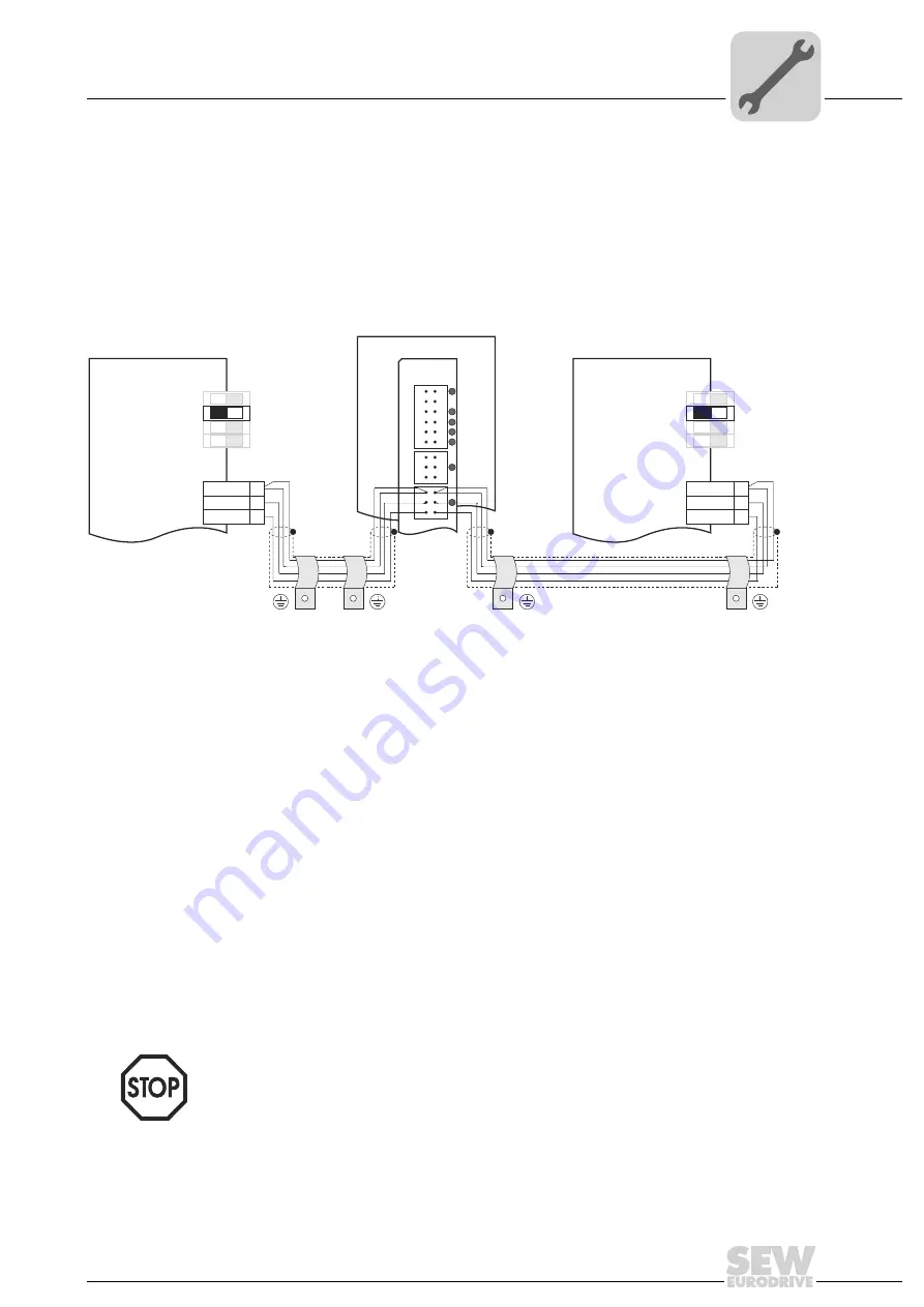
20054AXX
Figure 6: CAN 1 system bus connection taking the example of a MOVIDRIVE
®
MDX60B/61B drive inverter
MDX61B
DGND
DGND
S12
S12
S11
S11
S13
S13
S14
S14
ON
ON
MDX60B/61B
MDX60B/61B
X12
X12
OFF
OFF
SC11
SC11
2
2
1
1
3
3
SC12
SC12
DHP11B
X31
X32
X33
1
2
3
1
2
3
1
2
3
2
3
1
•
There must not be any potential displacement between the units connected via the
CAN 1 system bus. Take suitable measures to avoid potential displacement, such as
connecting the unit ground connectors using a separate cable.


