


Manual – XFE24A EtherCAT Fieldbus Interface
39
7
EtherCAT introduction
Motion Control via EtherCAT
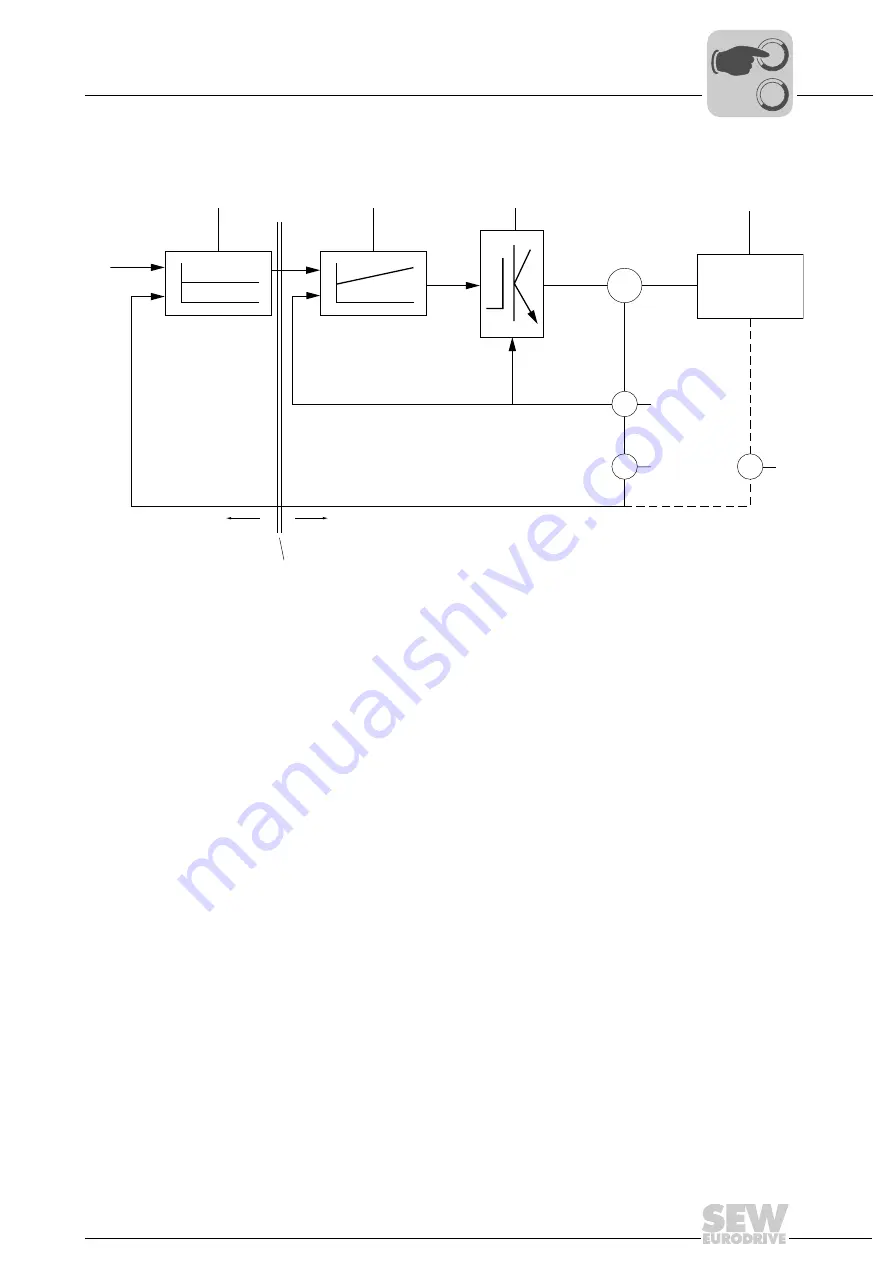
7.1.1
Speed setpoint interface (Velocity mode)
In Velocity mode, the controller transmits a speed (or velocity) setpoint to the servo in-
verter. The position actual value is read by the servo inverter or a separate encoder.
In Velocity mode, the servo inverter is a simple speed control element. The time slices
of the controller, the bus transmission and the internal processing cycle of the servo in-
verter and of external encoders, if applicable, must be synchronized to one another.
Referencing of the position, monitoring of permitted travel ranges or limit switches, load-
dependent ramp specification and lag error monitoring are realized in the higher-level
controller and are not tasks of MOVIAXIS
®
.
To prevent unwanted, high acceleration values for larger control intervals (>1 ms), the
speed setpoint is not directly adopted by MOVIAXIS
®
, but interpolated linearly. This
means for a setpoint cycle of 5 ms that the controller sets the required speed change in
the MOVIAXIS
®
not every 5 ms as one large step, but rather as 5 small steps of 0.5 ms.
61478AXX
Figure 15: Velocity mode – Cascade with fieldbus interface
M
V
X
X
X
ref
v
ref
t
ref
X
act
v
act
[3]
[2]
[1]
[4]
[5]
[C]
[A]
[5]
[6]
[B]
[A]
Control
[B]
Fieldbus interface
[C]
Servo
inverter
x
ref
Position setpoint
[1]
Position controller
x
act
Position actual value
[2]
Speed controller
v
ref
Speed setpoint
[3]
Output stage of the servo inverter
v
act
Actual speed value
[4]
Driven machine
t
ref
Torque setpoint
[5]
Encoder (V = speed; X = position)
[6]
Optional encoder
0
0
I
Содержание 1821 2492
Страница 2: ...SEW EURODRIVE Driving the world...
Страница 66: ......
Страница 67: ...SEW EURODRIVE Driving the world...