8
9
Installation
Installation
NOTE:
All Séura drawing packages indicate generalized nominal residential wood
framing construction, and are not indicative of any particular building code.
It is the installers responsibility that all electrical, audio/visual, and framing
construction are code compliant to the municipality in which the product is
being installed. Modifications made to Séura recommendations are at the
sole discretion of the installer and release Séura of all liability.
Inspect the desired location for installation and be aware of all electrical
wiring pathways, water pipes, gas lines, or other potentially hazardous
conditions that may exist to protect from accidental damage during creation
of on-site conditions.
Ensure all required electrical specifications are adhered to and have been
installed by the appropriate individuals and are code approved.
Ensure all framing requirements, if needed have been completed to building code and pose no structural issues.
It is REQUIRED that this product is plugged into an electrical outlet protected by a Ground Fault Circuit Interrupter (GFCI) to protect against electric
shock, fire, and/or injury. Failure to do so will void any warranty for this product.
Only qualified individuals should attempt to service the product. Removing covers can expose you to high voltage and other dangerous conditions.
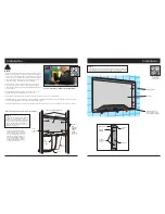
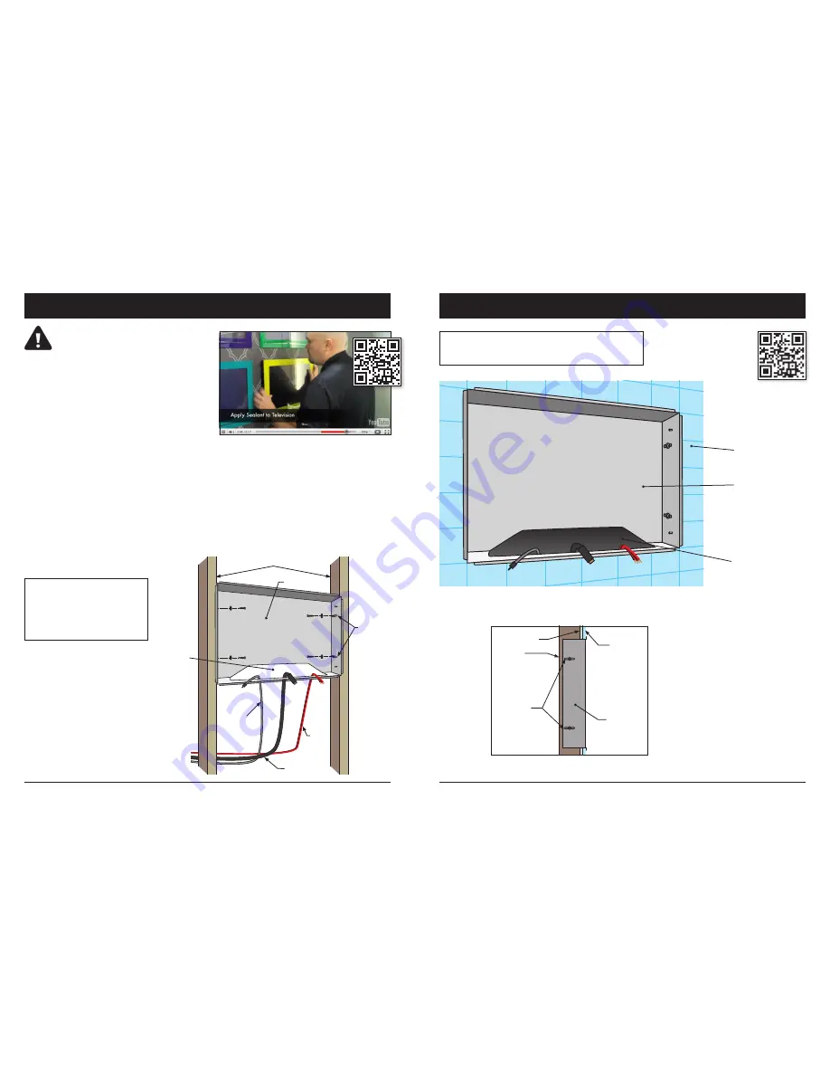
Step 1
Install back box to framing members using the
provided four screws and washers through
screw-mounting slots in back box. Ensure that
the front of the box is flush with finished wall
and mounting tabs will rest on finished wall
surface. Feed power and other desired cords
through pass-through port.
Read all installation instructions before beginning installation.
BACK BOX
VERTICAL FRAMING MEMBERS
SCREW
INTO
FRAMING
MEMBERS
USING
SCREW-
MOUNTING
SLOTS (4)
PASS-
THROUGH
PORT
LOW-
VOLTAGE
POWER
AUDIO
VIDEO
Note: Do not overtighten mounting
hardware. Back box should fit snuggly
between framing members. If the fit is
poor, and overtightening occurs, the
back box may deform, resulting in a
poorly sealed installation. If the back
box doesn’t fit well between framing
members, shim the framing members
for a square and stable fit.
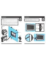
Step 2
While keeping cord ends outside the back box pass-through port, finish the wall
tight to the edges of back box, removing any gap. Once complete, the final wall
surface should be flush with the front edge of the back box as shown.
BACK BOX
MAINTAIN CORDS IN
PASS-THROUGH PORT
DURING WALL FINISHING
FINISHED WALL
FINISHED
WALL
WALL BOARD
FRAMING
MEMBER
SCREW
MOUNTING
SLOTS
BACK BOX
Scan to watch the 2-minute installation video
Scan to watch
the 2-minute
installation video
Содержание Hydra HY-19. 5
Страница 12: ...22 23 Notes Notes ...


