8
SESAMO
DUALCORE
The
RD100
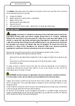
automated system (in addition to the parts from A to F and from K to P) consists
of the following parts (ref. Fig. 5/A):
Q-
emergency battery
R-
Master gearmotor with encoder - type 63x55
S-
Master control unit
T-
bistable electro lock (optional)
U-
Slave control unit
V-
Slave gearmotor with encoder - type 63x55, including belt tensioning
CASE WALL FIXING
DANGER: the phases of installation and fixing of the automated system involves the
movement of heavy parts and tools at heights greater than 2 or 3 meters. Accidental
falling of the heavy tools and parts presents a high risk to personnel and objects in the
vicinity. To reduce this risk, before performing the installation or maintenance, cordon off
a safe zone around the working area and prohibit access to any personnel not involved in
the operation and remove any objects that may be damaged. To reduce the risk to the
personnel in charge of the operations, the personnel must wear personal protective
equipment, in particular a helmet, safety shoes and cut-resistant gloves.
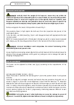
Remove the screws then remove the cover following the sequence shown in fig.7.
Remove the carriages following the procedure below:
-
disconnect the belt attachment bracket from the carriage ref.A fig.11 by undoing screws
C.
-
loosen the screw of the anti-derailing roller ref.D fig.9 and lower it fully.
-
remove the carriage
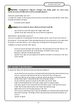
To make it easier to fix the case to the wall, the internal components can be moved or
removed by undoing the screws that attach it to the screw channel on the roof of the
automated system, as shown in Fig.6.
WARNING: before moving or removing the internal components, note their positions
or trace markers on the case so that they are reinstalled in the correct positions.
Inspect the surface to which the case will be fixed. If the surface is not sufficiently smooth,
level it using spacers. The automated device crossbeam can be deformed if fixed on a too
irregular surface.
Ensure that the structure to which the case and subsequently the sliding leaves will be fixed
is strong enough and well anchored to the building.
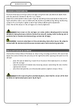
Fix the case to the support via the hexagonal screws M8, of a suitable length, through the
eyelets provided (fig.8). Ensure the screws and washers are suitable for use with the material
of the structure to which the case is being fixed.
Содержание DUALCORE LH100
Страница 1: ...LH100 LH140 RD100 ENGLISH AUTOMATED SYSTEMS FOR SLIDING DOORS INSTALLATION MANUAL ...
Страница 44: ...44 SESAMO DUALCORE Fig A Fig B ...
Страница 45: ...45 SESAMO DUALCORE Fig 1 ...
Страница 46: ...46 SESAMO DUALCORE Fig 2 ...
Страница 47: ...47 SESAMO DUALCORE Fig 3 ...
Страница 48: ...48 SESAMO DUALCORE WARNING Exit way ONLY for RD100 Fig 4 ...
Страница 49: ...49 SESAMO DUALCORE Fig 5 ...
Страница 50: ...50 SESAMO DUALCORE Fig 5 A ...
Страница 51: ...51 SESAMO DUALCORE Fig 6 Fig 7 ...
Страница 52: ...52 SESAMO DUALCORE Fig 8 Fig 9 ...
Страница 53: ...53 SESAMO DUALCORE Fig 9a Fig 10 ...
Страница 54: ...54 SESAMO DUALCORE Fig 11 Fig 12 ...
Страница 55: ...55 SESAMO DUALCORE Fig 13 Fig 14 Fig 15 ...
Страница 56: ...56 SESAMO DUALCORE Fig 16 Fig 16a ...
Страница 57: ...57 SESAMO DUALCORE Fig 17 Fig 17a ...
Страница 58: ...58 SESAMO DUALCORE Fig 18 Fig 19 Fig 20 ...
Страница 59: ...59 SESAMO DUALCORE Fig 21 Fuses 6 3A T J ...
Страница 60: ...60 SESAMO DUALCORE Fig 22 ...
Страница 61: ...61 SESAMO DUALCORE Fig 23 1 Fig 23 2 ...
Страница 62: ...62 SESAMO DUALCORE Fig 24 PARAMETER 30 1 ...
Страница 63: ...63 SESAMO DUALCORE Fig 25 PARAMETER 30 1 Exit way ...
Страница 64: ...64 SESAMO DUALCORE Fig 25 A ...
Страница 65: ...65 SESAMO DUALCORE Fig 26 ...
Страница 66: ...66 SESAMO DUALCORE Fig 27 PARAMETER 31 1 ...
Страница 67: ...67 SESAMO DUALCORE Fig 28 PARAMETER 31 0 ...
Страница 68: ...68 SESAMO DUALCORE Fig 29 ...
Страница 69: ...69 SESAMO DUALCORE Fig 30 Fig 31 ...
Страница 71: ...71 SESAMO DUALCORE Fig 33 ...
Страница 72: ...72 SESAMO DUALCORE Fig 34 ...


