22
Installation
-48 VDC Remote Power Manager
Installation and Operations Manual
NEBS GR-1089-Core Information
This product is suitable for installation in a Common Bonding Network (CBN).
“
WARNING:
The intra-building port(s) of the equipment or subassembly is suitable for connection to intra-building or
unexposed wiring or cabling only. The intra-building port(s) of the equipment or subassembly MUST NOT be metallically
connected to interfaces that connect to the OSP or its wiring.
These interfaces are designed for use as intra-building interfaces only (Type 2 or Type 4 ports as described in
GR-1089-CORE, Issue 5) and require isolation from the exposed OSP cabling. The addition of Primary Protectors is not
sufficient protection in order to connect these interfaces metallically to OSP wiring.”
“Intended to be installed in Network Communications Facilities and in locations where the NEC applies.”
This product has a common DC return (DC-C) terminal.
In the DC-C configuration, the ampacity of the conductor connecting the equipment frame to the BR conductor
shall
be equal
to or greater than the ampacity of the associated BR conductor.
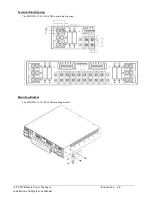
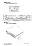
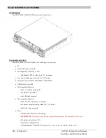
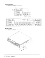
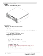
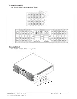
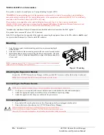
Mounting
1.
Select the appropriate bracket mounting points for proper mounting depth
within the rack.
2.
Attach the brackets to these mounting points with two screws for each bracket.
3.
Install the enclosure into your rack, using the slots in each bracket. The slots
allow about ¼ inch of horizontal adaptability to align with the mounting holes
of your rack.
NOTE:
A mounting bracket kit for 23” wide racks or cabinets is available. For more information,
contact your Server Technology sales representative.
Attaching the Expansion Module
Connect the -48 VDC Remote Power Manager with the provided RJ12 crossover cable at the Link port on the unit.
NOTE:
The overall length of the RJ12 crossover cable should not exceed 10 feet.
Connecting to the Power Source
NOTE:
Reverse polarity will damage the unit. Verify proper polarity before connecting to a power source.
1.
Verify power source polarity and remove the fuses/open circuit breakers for all outlet terminal pairs.
2.
Attach the appropriate input power cable(s) for your installation’s operating voltage.
3.
Attach the opposite end of the power cable(s) to the power source.
Connecting Devices
1.
Keep the On/Off switch on the device in the off position until after it is plugged into the outlet.
2.
Connect devices to the outlets on the -48 VDC Remote Power Manager.
Always disconnect ALL power supply cords before opening to avoid electrical shock.
Afin d’éviter les chocs électriques, débranchez TOUTES les cables électrique avant d’ouvrir.
Immer ALLE Netzleitungen
auskuppeln vor den Aufmachen um elektrischen Schlag zu vermeiden.
Figure 1. Mounting

