APPEND
I
X A. REAR-PANEL PORT DESCR
I
PT
I
ONS
A Rear-panel port descriptions
A.1 PWR-COM2&3/USB
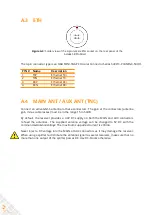
Figure A-1:
Solder view of the 7-pin female PWR-COM2&3/USB socket on the rear
panel of the AsteRx SB ProDirect
The 7-pin connector type is an ODU M
I
N
I
-SNAP F Circular Connector Series S40F1C-P07MCD0-500S.
PIN #
Colour
COM mode
USB mode
Comment
1
Red
PWR
Not
connected
5-36 VDC input (1.3A)
Pink wire with Red heat-shrink tube
2
Black
GND
GND
Ground
Brown wire with Black heat-shrink tube
3
Green
RxD3
USB D-
EITHER
Serial COM3 receive line
OR
Negative USB 2.0 FS device node.
Selection is done via pin 7.
4
Yellow
TxD3
Not
connected
Serial COM3 transmit line
5
Grey
RxD2
USB D+
EITHER
Serial COM2 receive line
OR
Positive USB 2.0 FS device node.
Selection is done via pin 7.
6
White
TxD2
Not
connected
Serial COM2 transmit line
7
Blue
Not
connected
VBus
4.4-5.25 V input.
If present
, USB-mode is selected.
If not present
, UART Serial COM mode is
selected.
32
Содержание AsteRx SB ProDirect
Страница 1: ...AsteRx SB ProDirect User Manual ...
Страница 35: ...APPENDIX A REAR PANEL PORT DESCRIPTIONS 35 ...


