SEON Explorer TX8 Скачать руководство пользователя страница 24

Explorer TX8


Installation Guide

24 

700-0157 R001 

configuration as a file to upload to other DVRs.

vMax Web Laptop Configuration

The TX8 DVR can be managed via the vMax Web internet portal. Microsoft

®

 Internet Explorer

®

 7.0 or 

higher version is required. Make sure the DVR and other system components are already installed and 
configured in order to access the DVR via vMax Web. Connect the laptop to the DVR using an RJ-45 
Ethernet cable.

To configure your laptop:

Configure your laptop to obtain IP addresses automatically, using DHCP (Dynamic Host Configuration 
Protocol). If it is not configured to DHCP, or you need to verify the setting, then follow these steps to 
configure your laptop.

25

Navigate to Windows Local Area Connection properties in Windows 7 or XP as follows:

Windows 7

: click 

Start

 > Control Panel > Network and Internet > Network and Sharing > Local Area 

Connection.

Windows XP

: click 

Start

 > Control Panel > Network Connections > Local Area Connection.

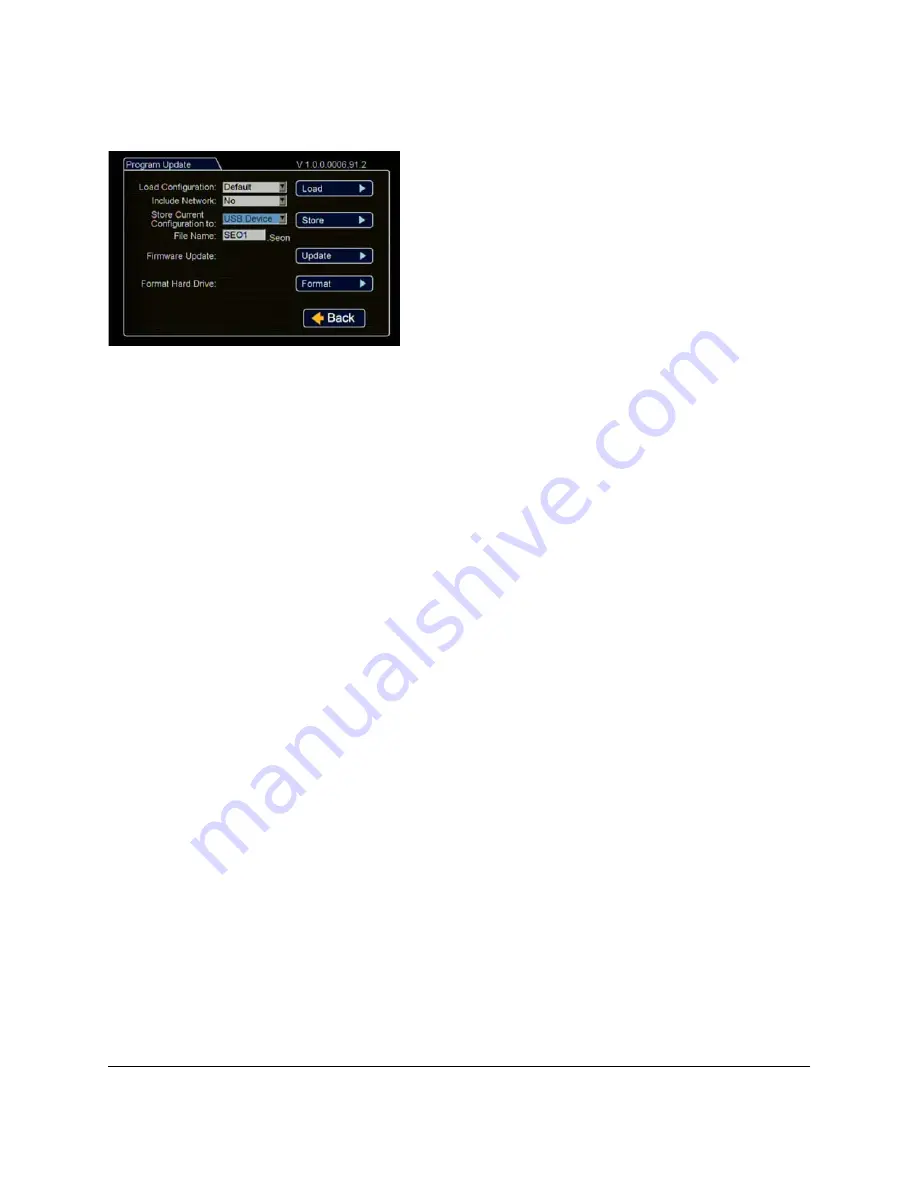
Select USB Device as the file saving destination. Plug a 
USB memory device into the front of the DVR. Click 

Store


to save the file on the USB memory device.

Load

: For details on uploading configurations to the DVR, 

see DVR Configuration Uploads, on page 29.

Update

: Firmware updates can also be delivered by a USB 

device. The DVR will reboot when done.

Format

: Format the hard drive when the configuration is 

complete and before final delivery of the installation to the 
customer. 

Click 

Back

 to save the menu settings.

Figure 29

Program Update Menu

Содержание Explorer TX8

Страница 1: ...nfigure the Seon Explorer TX8 DVR The DVR can be installed horizontally or vertically The DVR requires configuration as part of the install process The TX8 DVR is secured with a locking front cover and a cable cover Two cable grommets and two knockouts on the cable cover allow for wiring to enter from the left side right side or back of the unit ...

Страница 2: ...ail Notifications on page 38 Updating the Firmware on page 37 Configuration Menu Descriptions on page 40 Dimensions on page 66 Related Documents on page 66 Customer Service Contact Information on page 66 Tools and Equipment Before installing check that all system components are present and undamaged Required installation tools Drill with bit to cut 1 cabling hole Phillips bit 2 for 6 32 x 3 16 scr...

Страница 3: ...e options selected Optional Equipment Explorer TX8 DVR with hard drive locking front cover cable cover and mounting plate Cameras up to 8 and extension cables 2 3 6 pin over mold connectors Alarm Switch and cable Alarm input harness Ignition input harness Speed harness Adapter harness Diagnostic Button and expansion harness not shown Smart Reach Mobile GPS receiver RGY Illuminator and expansion ha...

Страница 4: ...e Wi Fi 1 For speed tracking use a GPS receiver or speed harness For ease of installation and better speed tracking Seon recommends using a GPS receiver 2 The Diagnostic Button and alarm input harness are optional and require the adapter harness 3 An optional Laptop can be used from the Ethernet outputs located on the front panel 4 An optional LCD Monitor can be used from the video outputs located...

Страница 5: ...unusable Table 1 Choosing a Location and Other Installation Requirements Ventilated location Install the DVR away from any sort of heat outlet heater or AC blower Do not operate the DVR in a closed in area or restrict ventilation in any way The DVR requires air circulation to maintain optimum operating temperature and provide best performance Mount to secure surfaces only Do not mount the DVR to a...

Страница 6: ...or lock and remove the front cover from the unit to access the front panel Verify there is a hard drive inside the DVR See Figure 2 3 Determine where the wiring and camera cables will enter the unit on the left side right side or back 4 Remove the necessary knockout s insert plugs and cable grommets See Figure 3 5 Use the mounting plate to mark the desired position of the DVR and drill the four mo...

Страница 7: ...components Camera Installation Install the cameras according to the product documentation that is included with the camera Feed the cables through the large cable grommets one at a time or cut a space from the edge of the cable cover to the grommet and slide the cables into the grommet Figure 4 TX8 Attaching to Mounting Plate CAUTION Wiring Damage Route the wiring and cables away from sharp edges ...

Страница 8: ...TX8 System on page 4 Alarm Button Installation To install the alarm button 1 Mount the Alarm Button into a hole and attach to the alarm input harness using the micro fit connectors 2 Attach the black wire of the Alarm Button to the black wire of the Alarm Input harness 3 Attach the red wire of the Alarm Button to the red wire in the Alarm Input harness 4 Connect the Alarm Input harness connector t...

Страница 9: ... 1 Connect the DVR s back panel alarm input harness connection 2 pin so that pin 1 red wire is toggled to a 12 VDC to 24 VDC source to trigger power 2 Connect or remove the black wire of the alarm input harness 3 In the DVR Alarm Settings configuration menu configure as follows Select Alarm 1 Set the Alarm Duration 1 5 or 10 minutes Set the Alarm Input to Normally Closed Set the pre alarm record d...

Страница 10: ...Diagnostic Button to cause an alarm event to be recorded by the DVR To install the Diagnostic Button see the Diagnostic Button Installation Guide part number 700 0142 RGY Illuminator Installation Optional When installed the RGY Illuminator LED displays DVR status conditions To install the RGY Illuminator see the RGY Illuminator Installation Guide document number 700 0139 Important If you are using...

Страница 11: ...se adverse operation of the DVR However if a power cable extension is required ensure that the voltage drop does not exceed 1 0 volt by using the correct cable size See Table 2 Connections for power cables should be soldered and sealed to prevent corrosion and voltage drop across connections Once complete ensure the DVR s voltage display is above 11VDC with the vehicle off and the DVR recording Im...

Страница 12: ...le ignition Configure the DVR to required specifications locally using the remote control or the trackball mouse or remotely by accessing vMax Web over the internet using a PC See Typical DVR Configuration Settings on page 13 Confirm the LAN HDD and PWR status indicators on the DVR front panel work properly Confirm that all the cameras and audio sources are operating properly Test audio video reco...

Страница 13: ...VR Configuration Settings on page 13 G Sensor field calibration cannot be preformed remotely Typical DVR Configuration Settings Once the unit is installed and power and cabling settings are complete set up the DVR in the configuration menus These are the typical DVR configuration settings If the customer or installer wishes to further modify the settings see Configuration Menu Descriptions on page...

Страница 14: ... in Figure 10 The screen items can be configured in the main menu Basic DVR configuration steps 1 In the live view right click anywhere to show the DVR Main menu Left click on Configuration 2 In the Configuration menu click Time Date Figure 10 On Screen Display during Live Viewing and Recording Figure 11 Main Menu Figure 12 Configuration Main Menu ...

Страница 15: ...rd with Text or with Numbers Time Format Choose 12 or 24 hour time display format Time Input the correct time Date Format Select the date format Date Input the correct date Note If GPS is installed and GPS time is selected in the Alarm Signal Speed and GPS settings then the date and time automatically update when the GPS detects satellites Auto Daylight Saving should be left On and dates left as d...

Страница 16: ...Typical camera titles are Front Step Mid Rear Stop Arm Click Back to save the menu settings Figure 15 Titles and Display Menu Default Setting Choose a monitor view setting which will display all the cameras you have connected Display Switch Leave On to display the time and date Switch To If a rear view camera is installed select the channel that will display the rear camera view when the following...

Страница 17: ...ave the menu settings Figure 17 Diagnostic Display Menu Repeat Record Leave at default for the hard drive to loop and record over the first recordings when it is full Record Delay On Time Leave at default to let the bus voltage settle after the bus starts up to prevent voltage drops affecting the DVR Record Delay Off Time Set to 10 20 minutes to keep the DVR and cameras on after the ignition turns...

Страница 18: ...default settings unless you have special requirements Quality Leave the channel quality at default settings unless you have special requirements Audio Leave audio settings On unless the camera is mounted on the exterior of the vehicle Click Back to save the menu settings Figure 19 Camera Settings Menus CAUTION Video Loss Events When a DVR is installed with less than the full complement of cameras ...

Страница 19: ... Timer Settings Menus Label For signals 1 5 labels are provided for left turn stop brake warning light and right turn The labels can be edited and changed Signals 6 10 are available for advanced signal wiring if required Maximum 3 character Level Set all signal levels as required Choose Active High if the circuit you are installing into rests at 0 VDC and goes to 12 VDC when active Choose Active L...

Страница 20: ...witch type used Pre Alarm Select how many seconds of pre alarm video is included in the flagged alarm recording Email Leave at default unless instructed otherwise Wake Leave at default unless instructed otherwise Click Back to save the menu settings Figure 22 Alarm Settings Menu Speed Display If GPS is installed select GPS GPS sensors are replacing the vehicle speed sensor calibration system Speed...

Страница 21: ...ck to save the menu settings Format the drive after GPS settings are complete Figure 24 GPS Settings Menu CAUTION Recording over Multiple GPS UTC Reference Settings Whenever the GPS UTC reference setting is edited format the DVR hard drive before the DVR starts recording This is to prevent the DVR from accidentally recording over the same time period in different time zones That can happen if a DV...

Страница 22: ...urfaces Output Select an alarm or signal output for the settings if required Click Calibrate to open the Calibration menu From the drop down menu select the DVR front surface Click Field Calibrate for the G Sensor to set the X Y Z axis planes based on the mounting surface selection Click Back to save the menu settings Figure 25 G Sensor Menu Setting Type Leave at default Static IP setting Use the ...

Страница 23: ... level user has complete DVR control Configure level cannot edit user levels or IP settings Playback level can only view and archive recordings Click Back to save the menu settings Figure 27 Network Settings Menu CAUTION DVR Password Security The default password is 11111111 For security purposes Seon recommends that the user default login and system settings passwords should be changed Seon is no...

Страница 24: ...ow these steps to configure your laptop 25 Navigate to Windows Local Area Connection properties in Windows 7 or XP as follows Windows 7 click Start Control Panel Network and Internet Network and Sharing Local Area Connection Windows XP click Start Control Panel Network Connections Local Area Connection Select USB Device as the file saving destination Plug a USB memory device into the front of the ...

Страница 25: ...Properties The Local Area Connection Properties window appears 27 In the Local Area Connection Properties window select the click to highlight the current Internet Protocol Version in Windows XP select Internet Protocol TCP IPv4 and then click Properties Figure 30 Local Area Connection Properties window Figure 31 Local Area Connection Properties window ...

Страница 26: ...llation Guide 26 700 0157 R001 The Internet Protocol Version Properties window appears 28 In the Internet Protocol Properties window select Obtain an IP Address Automatically Figure 32 Internet Protocol Properties window ...

Страница 27: ...aptop Local Area Connection should report limited connectivity using an Automatic Private IP Address Confirm by opening your network connections as shown in Figure 33 In very rare instances the laptop may select the same IP address http 169 254 1 1 used by the DVR and cause a conflict If this is the case manually set the laptop IP address to http 169 254 1 2 as shown in Figure 34 1 APIPA is a feat...

Страница 28: ...wing credentials to access the internet browser user interface The user name is case sensitive 7 Click OK or press enter on the keyboard to display the vMax Web interface live view screen Figure 35 Login Screen CAUTION DVR Password Security The default password is 11111111 For security purposes Seon recommends that the user default login and system settings passwords should be changed Seon is not ...

Страница 29: ...ysical access to the DVR an LCD Monitor and a USB mouse To load a configuration update to the DVR the USB memory device must be formatted by a Windows based computer using the FAT32 file format To upload a configuration update on the TX8 via USB 1 Copy the configuration file to the root of the USB memory device folder 2 Power up the DVR using the vehicle ignition 3 Connect the LCD monitor and USB ...

Страница 30: ...keeps your existing network settings Figure 37 System Settings Menu Figure 38 Program Update Menu Select File Important The Load Configuration drop down list displays alphabetically the first ten configuration files on the USB memory device Only file names with 4 or less characters can be displayed CAUTION DVR Communication Disruption Risk Avoid unintentionally changing the DVR network settings wh...

Страница 31: ...ion Guide 700 0157 R001 31 9 Click Load 10 In the Confirmation window click Yes to proceed or No to cancel Figure 39 Program Update Menu Include Network Figure 40 Program Update Menu Load Figure 41 Confirm Configuration Load ...

Страница 32: ... the Configuration menu click Title Display and in the Titles and Display menu update the text in the Main_Title field 13 Click Back to save 14 Remove the USB memory device 15 Turn off the DVR restart the DVR and confirm that the new configuration settings have been applied Figure 42 Click Back to Save Configuration Figure 43 Titles and Display Menus ...

Страница 33: ... up the DVR using the vehicle ignition 3 Open Internet Explorer and in the address bar type in the DVR IP address The default IP address is http 169 254 1 1 4 If necessary agree to Windows Run Add On requests 5 At the login prompt enter a user name and password User names and passwords are case sensitive 6 Click Login vMax Web opens with the DVR cameras displaying in Live view Figure 44 Login vMax...

Страница 34: ...load 10 In the Program Update Settings area below the Load Configuration from File field select Browse to open the computer search window Figure 46 vMax Web System Settings CAUTION Risk of Network Settings Loss Configurations uploaded to the DVR with vMax Web do not get written to the DVR until it powers down and restarts If anyone edits the DVR settings locally after this configuration is uploade...

Страница 35: ...page dialog click OK to start the configuration upload 14 If necessary agree to Windows Run Add On requests Figure 49 Windows File Search Important For consistency Seon recommends that the configuration upload file name should be kept to four characters maximum seon in the event that the file needs to be loaded to the DVR from the USB port The DVR USB upload interface supports only four characters...

Страница 36: ... Display menu update the text in the Main_Title field 17 Click Save to save the settings to the DVR 18 Power down and restart the DVR 19 Login with vMax Web and refresh the vMax Web browser view 20 Confirm that the new configuration settings are in place Figure 52 Loading Complete Figure 53 vMax Web Titles and Display Menu Figure 54 ...

Страница 37: ...on 22 Insert the USB memory device with the new firmware version into the USB port on the DVR 23 After the DVR has started go to the System Settings menu Program Update 24 Click Update 25 In the confirmation window click Yes to proceed or No to cancel 26 Once the update is finished the DVR will automatically restart when the ignition is on 27 Remove the USB memory device CAUTION Equipment damage D...

Страница 38: ...ecording can be viewed or the event can be addressed Typically a dedicated server is required to support network email addresses 1 In the vMax Web Network Email settings window populate the E mail configuration fields as required 2 In the Alarm configuration menu select the E mail check box for each alarm configuration requiring email notification Figure 56 System E mail settings CAUTION DVR Passw...

Страница 39: ...em menu select E mail from the Disk Full and HD Failure drop down menus 4 Click Save If the configured alarm or system events occur the email will be sent when the DVR is within range of a Smart Reach access point Figure 58 EX TR series DVR Configure tab Figure 59 ...

Страница 40: ...oltage Display Time Date Display HDD Size Display Full Display Alarm Count Display Fan Failure Not ation G Sensor Display Internal Temperature Display Ignition State Display Time Date Time Format Time Date Format Date Auto Daylight Savings DST Settings Start Date From To End Date From To Alarms Alarm Alarm Duration Alarm Input Pre Alarm Record Channel 1 4 Speed Quality Resolution Email Wake Speed ...

Страница 41: ...Subnet Mask Default Gateway DNS Server MAC Address User Levels 1 6 Name Password Level DDNS Settings DDNS Server User Name Password Record ID FQDN Host Name System Disk Full HD Failure Password Enable Password Audio Output Channel Diagnostic Indicator Program Update Load Con tion from USB Include Network Store Default Con guration to USB Firmware Update Format Hard Drive Load Store Update Format E...

Страница 42: ...mat Set the time in 12 hour or 24 hour format 12 Hour 24 Hour Time Set the time for the DVR 12 00 am to 11 59 pm for 12 Hour format 00 00 to 23 59 for 24 Hour format Date Format Set the preferred date format mm dd yyyy dd mm yyyy yyyy mm dd Date Set the date for the DVR Depends on selected Date Format setting Auto Daylight Saving Auto Daylight Saving set to On automatically adjusts the internal cl...

Страница 43: ...figuration Items Menu Item Description Values Default Start Date Set the week day and month for daylight saving to start 2nd Sunday Mar From Set the time for daylight saving to start 02 00 AM To Set the time for daylight saving to end 03 00 AM End Date Set the week day and month for daylight saving to end and return to Standard Time 1st Sunday Nov From Set the time for daylight saving to start 02 ...

Страница 44: ...d other camera view overlay options Figure 64 Titles and Display Menu Table 5 Titles and Display Configuration Items Menu Item Description Value Default Main Title Set a title Main_Title Maximum 32 characters Main Title Display Show or hide the main title display On Off Camera 1 to Camera 8 Set a title Camera01 to Camera08 Maximum 8 characters ...

Страница 45: ...ime date display On Off Switch To When Display Switch is set to On set the rear monitor view Front CH1 to CH8 Sequence Switch On When Display Switch is set to On set the trigger that will make the rear monitor switch to the view selected in Switch To setting Alarm Signal Timer Alarm Signal or Timer When Display Switch is set to On set which specific trigger will make the rear monitor switch from t...

Страница 46: ...play Display the system input voltage On Off Time Date Display Display the time date display On Off HDD Size Display Display the hard drive size On Off Full Display Display the percentage of the hard drive space used On Off Alarm Count Display Display the current alarm count 1 to 9 Alarm count resets to 0 when the DVR is restarted On Off Internal Temperature Display Display the ambient temperature...

Страница 47: ...us F Fahrenheit Off Hard Drive Hours Displays the amount of time in hours that the hard drives have been recording since new After 20 000 hours of recording time contact Seon Design to confirm hard drive health status with a DVR hard drive check General Health A self check of the hard drive sub systems indicates operating condition of the DVR hard drives Green Red Ethernet Connections Indicates if...

Страница 48: ... The alarm duration is the length of time after an alarm has been received that the video is recorded at the alarm speed and quality 0 5 10 30 sec 1 3 5 10 15 20 30 45 min Alarm Input Available only for Alarm 1 Set the alarm input to normally open or normally closed N O N C Pre Alarm Record Set the DVR to record alarm data trigger time duration and pre alarm time with the alarm event Off 5 sec 10 ...

Страница 49: ...ne minute to power up and start recording depending on environment conditions Configure Alarm 1 as follows In Alarm Input set Alarm 1 to N C In Alarm Duration select one minute or greater Wire Alarm 1 as follows Connect the DVR s back panel alarm connection 2 pin so that pin 1 red wire is toggled to a 12V to 24V source to trigger power The black wire of the alarm harness can be connected to Ground...

Страница 50: ...On screen display text for brake signal BRK maximum 3 characters Signal 4 On screen display text for warning lights signal WRN maximum 3 characters Signal 5 On screen display text for right turn signal RT maximum 3 characters Signal 6 User generated on screen display text S06 maximum 3 characters Signal 7 S07 maximum 3 characters Signal 8 S08 maximum 3 characters Signal 9 S09 maximum 3 characters ...

Страница 51: ...librate the DVR to the vehicle s speed signal by driving for one mile or kilometer in Calibration Mode The DVR counts the pulses from the speed sensor and then converts a pulse rate into speed The actual distance driven during calibration determines the unit of the speed For example to have speed recorded in MPH drive for one mile in Calibration Mode To have speed recorded in KPH drive for one kil...

Страница 52: ...rm Using GPS Geo fencing lets the administrator set a designated geographic radius If the vehicle deviates from this area the DVR sounds an alarm Enable or disable the fencing alarm to record an alarm or not Off ALM 1 ALM 2 ALM 3 ALM 4 Coordinate Style Circle Set the coordinate style to a circle Enter information for LAT and LONG as displayed in Figure 72 Circle Rectangle Circle Center LAT Set the...

Страница 53: ...djusted to fit specific requirements The lower the settings the higher the chances are of generating false alarms Figure 73 G Sensor Settings Menu Table 13 G Sensor Settings Configuration Items Menu Item Description Value Default Axis X Forward Back axis Y Left Right axis Z Vertical axis Vector Combination of Z and Y axes Current Display only This field displays to current values measured by the G...

Страница 54: ...the X Y and Z axis orientations To calibrate the G Sensor 1 Make sure the DVR is mounted securely in a horizontal or vertical position 2 From the drop down menu select the DVR front surface 3 Click Field Calibrate for the G Sensor to set the X Y Z axis planes based on the mounting surface selection When the process is complete a Calibration Complete message is displayed 4 Click Back to save settin...

Страница 55: ...nables a time delay after switched power to the DVR is turned on 0 30 sec 1 5 10 20 30 45 60 min Record Delay Off Time Enables a time delay to continue recording after the switched power to the DVR is turned off 0 15 30 sec 1 5 10 20 30 45 60 min Power Delay Off Time Enables a time delay after the record delay off time expires to keep the DVR on but not recording The control connector on the DVR b...

Страница 56: ...X8 has a maximum available frame rate of 120 frames per second available which can be distributed between up to 8 cameras Off 1 5 7 5 10 15 30 fps Quality Set the picture quality option The DVR uses H 264 video compression to extend the recording time on the hard drive See Estimated Recording Time tables on page 9 1 2 3 4 Resolution Set the recording resolution in pixels The higher the recording r...

Страница 57: ...6 Timer Settings 1 to 10 Menu Item Description Value Default Enable Timers Enables preset times for recording Off On Day Set the timer to record on a specific day daily every weekday WDY or only on the weekend WND DLY WLY WND SUN MON TUE WED THU FRI SAT Start Set in 12 hour format Set in 24 hour format 12 00 AM to 11 59 PM for 12 hr format 00 00 to 23 59 for 24 hr format End Set in 12 hour format ...

Страница 58: ...Technical Support Figure 78 Network Settings Menu Table 17 Network Settings Configuration Items Menu Item Description Value Default Setting Type For network settings consult your IT administrator to configure the setting type and IP address If DHCP is used the subnet mask default gateway and DNS server are configured automatically Off Static IP a permanent address on the Internet assigned by the n...

Страница 59: ...vels Configuration Items Menu Item Description Value Default User 1 User 2 to 6 Name Six user names can be configured to have remote access to the DVR These are case sensitive Admin for User 1 Blank for User 2 to 6 Maximum 8 characters Password Set the password for each individual user 11111111 Maximum 8 characters Level Each user is assigned a specific access level Three levels are supported play...

Страница 60: ...ription Value Default DDNS Dynamic Domain Name Server Dyn DNS currently supported Maximum 64 characters User Name Set the user name Maximum 32 characters Password Set the password Maximum 32 characters Record ID This is typically a numeric string Maximum 16 characters FQDN Host Name The fully qualified domain name for the host I e mydvr myname dyndns com Maximum 64 characters ...

Страница 61: ... Figure 81 System Settings Menu Table 20 System Settings Configuration Items Menu Item Description Value Default Disk Full Set to send e mail notification when the disk is full Off On HD Failure Set to send e mail notification if the hard drive fails Off On Password Enable If set to On the STOP TEMP PWR button on the DVR is locked out and requires a password Off On Password The password is maximum...

Страница 62: ...own list will only show the most recent 10 configuration files on the USB device Default MEM1 MEM2 Include Network Select to include network information when the configuration is loaded NO YES Store Current Configuration Store the DVR configuration settings to a USB device USB Device MEM1 MEM2 File Name Set the file name of the configuration file you are saving SEO1 Maximum 4 characters Load Load ...

Страница 63: ...Explorer TX8 Installation Guide 700 0157 R001 63 Figure 84 Store DVR Configuration to USB Device Message Figure 85 Update DVR Firmware Message Figure 86 Formatting the Hard Drive Message ...

Страница 64: ...Value Default SMTP Server Set the server name Maximum 32 characters SMTP Port Set the SMTP port 25 1 through 9999 Authentication Set the authentication Login None User Name Set the user name when Login is selected Maximum 32 characters Password Set the password when Login is selected Maximum 32 characters Sender Set the sender e mail Maximum 64 characters Receiver Set the receiver e mail Maximum 3...

Страница 65: ...escription Value Default One Touch Download Set the video type to be downloaded See Using One Touch Download on page 11 Alarms Today Time From Date Set the month day and year Depends on the hard drive data From Time Set the time 12 AM to 11 PM for 12 hour format and 00 to 23 for 24 hour format To Date Set the month day and year To Time Set the time 12 AM to 11 PM for 12 hour format and 00 to 23 fo...

Страница 66: ...on Guide document number 700 0142 RGY Illuminator Installation Guide document number 700 0139 Customer Service Contact Information June 2012 Seon Design Inc All rights reserved Printed in Canada www seon com Important Specifications are subject to change without notice Figure 89 Explorer TX8 Dimensions Toll free telephone 1 877 630 7366 Telephone 604 941 0880 Email service seon com 295mm 11 19 32 ...

Отзывы: