


Final testing and adjustment
MPS-4100 product guide • • • 3 - 3
7. Make final adjustments at the Receiver to see if the signal can be further
improved.
8. Secure the Receiver in place.
If adjusting both the Transmitter and Receiver does not improve
the alignment, and the present received signal level is in the
Red, Yellow, or the first few Green LEDs, it may be necessary to
move the Receiver, the Transmitter, or both units slightly up or
down on the mounting posts.
If it is difficult to obtain an acceptable alignment level via the Alignment LED’s it
may be beneficial to connect a volt meter to the Receiver’s alignment test points
TP6 (+) and TP12 (-). The alignment voltage range is from 0 to 5 VDC. An
acceptable alignment measures above 3.5 VDC. Repeat the alignment procedure
while measuring the alignment voltage at TP6 and TP12.
Unstable zones (significant snowfall)
If you are in an area that experiences significant snowfall, the mounting height
and alignment procedure may differ from the standard procedures. In this type of
environment a hard paved surface is recommended for the microwave zone to
facilitate snow removal. Refer to Do’s and Don’ts a planning primer and Stacking
bistatic microwaves for information about installing and aligning the MPS-4100
Microwave system in environments with significant snow accumulation.
Final testing and adjustment
1. Verify that all alarm and supervision indicator LED’s are off. On units that do
not include a Communication Interface Card or network Transponder, ensure
the alarm relay is in the non-alarm state.
2. Move your hands or body in front of the Receiver to test for proper detection.
Look for the alarm LED to illuminate, and listen for the alarm relay to activate.
For network systems, verify the annunciation of a microwave alarm on the
alarm display and control system.
3. Walk into the microwave field at various points along the zone to verify
proper detection.
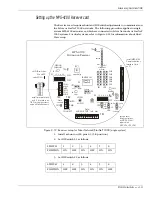
4. If it is necessary to increase the Microwave’s sensitivity, turn the Sensitivity Pot
(RV1) clockwise. To decrease the sensitivity, turn the Pot counter-clockwise
(see Figure 3-1).
Содержание MPS-4100
Страница 1: ...Product MPS 4100 Microwave Protection System Guide E6DA0102 003 Rev C Third Edition April 27 2009 ...
Страница 6: ......
Страница 70: ......