


System description
Page 10
Senstar LM100 Product Guide
alarms and in response to inputs. The highest priority setting is force OFF which is generally used
to disable the lights during daylight hours. When the force OFF setting is selected, alarm
conditions continue to be annunciated but the LEDs do not activate.
There are eight routine lighting schedules that can be applied to the luminaire zones. For
scheduled light control, the time ON, time OFF, days of the week and brightness are specified. For
example, a zone could be configured to turn ON at 50% brightness at dusk, switch to 25% at
midnight, respond to alarms at 100% brightness, and remain OFF during the daylight hours. For
Alarm response, luminaires can be turned ON, OFF, or strobed individually or in zones. The time
that the luminaires remain ON and their brightness are also specified. For example, the luminaire
that detects an intrusion attempt can be strobed and the zone it is assigned to can be turned ON. It
is also possible to configure a zone to provide lighting without intrusion detection. For example, a
number of luminaires could be used to provide walkway lighting and building entrance lighting.
These luminaires would be scheduled to turn ON at dusk and OFF at dawn. Alarm detection is not
desired for these luminaires so the detection for this group of luminaires would be disabled.
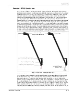
Senstar LM100 luminaire AP
The luminaire AP is the access point through which the distributed luminaires communicate with
the gateway device. It also functions as a standard luminaire providing intrusion detection and
routine lighting. A two-wire RS-485 connection between the AP and the gateway enables half-
duplex communication between the two devices. Individual luminaires are polled for status
information, and when a fence disturbance occurs, the luminaire detecting the disturbance
transmits the information. This information is passed over the wireless mesh network until it is
received by the luminaire AP. The luminaire AP sends the data to the gateway over the RS-485
connection. The gateway processes the data and triggers an alarm when the received signals
meet the criteria for a valid intrusion. The luminaire AP includes a 3 m (10 ft.) 4-conductor cable to
make the power and data connection to the gateway. The luminaire AP can be installed up to
100 m (328 ft.) away from the gateway by splicing in a suitable length of data/power cable. To use
the extended cable length requires a minimum 24 VDC power supply.
Senstar LM100 gateway
The gateway is the central controller for the Senstar LM100 system. It communicates with the
distributed luminaires through a 2-wire RS-485 connection to the luminaire AP. The gateway
receives the alarm and status information from the luminaires, and depending on the method of
alarm reporting, it either passes the data to the Silver Network Manager (NM) or it activates the
onboard outputs to signal alarm conditions and status information. System setup and configuration
for the luminaires is done using the Universal Configuration Module (UCM) through either a direct
USB connection to the gateway device, or remotely through the Silver Network Manager.
The gateway can be mounted outdoors on a post, either on, or separate from, the fence on which
the luminaires are installed. A rigid fixed post is recommended for outdoor applications. The
gateway can also be installed indoors or outdoors on a flat stable surface. Post-mounting
hardware is supplied for post sizes ranging from 4.5 cm to 12.7 cm (1¾ in. to 5 in.). The hardware
required for surface-mounting the gateway is customer-supplied. The gateway enclosure is hinged
on one side and includes a lockable latch (padlock not included).
The gateway includes ten input/output (I/O) ports, each of which can be configured as either an
input or an output. I/O option cards are available to provide an additional 4 inputs or 4 outputs.
There are two selectable control modes for the gateway’s I/O, local control mode and remote
control mode. The control mode is set in software, via the UCM. The default setting is local control
mode, in which the gateway controls the on-board relays to signal alarm and supervision
conditions (user selectable relay activation conditions). In local control mode, the inputs are used
to activate user specified luminaires (i.e., when the input goes high, activate one or more


