


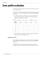


Configuration settings
7 - 6 • • • Intelli-FLEX II product guide
•
Hold the screwdriver loosely in your hand and flip your wrist so that the
blade of the screwdriver solidly impacts a link of the fence. This impact
should occur at least 30 cm (12 inches) from where the sensor cable is
mounted to the fence. This is a Medium Tap.
•
Practice this tap a few times until you become consistent. Practice tapping
consistently lighter, then consistently harder. These variations are similar to
those that occur when the fence is being cut.
•
You can read the intensity of your taps (set gain for about 25) on the
Configuration Module while it is in Level Mode.
You can also simulate a cut event by weaving a scrap piece of fence fabric wire
through the actual fence. Cut this piece and record the level. Now tap the fence
until you achieve the same level. This is an alternate method of simulating a cut
event. Tapping the fence using a screwdriver will achieve sufficient results.
Testing for proper intrusion detection
With the Gain adjustments confirmed, the system is ready to detect intrusion
events. Used the following procedures to confirm system response along the
fence.
Testing cut detection response in zone 1
1. Connect the Configuration module to the processor board. After it has
initialized, check to make sure that the Configuration module is in Monitor
mode with the
Zone 1
and
Cut
LEDs lit. The display will indicate the number
of Cuts that must occur to initiate an alarm. (Factory default is 4)
2. If the Configuration module is already connected press
Display Select
as
many times as required to set the Configuration module as described in step
1.
3. To simulate a cut event, tap the fence once with a medium size screw driver at
the intensity level at which minimum detection is desired. Use the same
intensity as you used during the gain setting procedure. (or slightly harder)
The
Time Window
LED is lit, the
Threshold
LED lights momentarily, and the
display has decreased in value by one.
4. Repeat step 3 until a cut alarm initiates.
5. When the cut alarm initiates the following will occur:
•
the
Zone 1
,
Cut
and
Alarm
LED’s light
•
the audible alarm is heard
•
L1
is displayed indicating that Zone 1 is in alarm
•
on the processor board, the
Zone 1
alarm LED is lit


