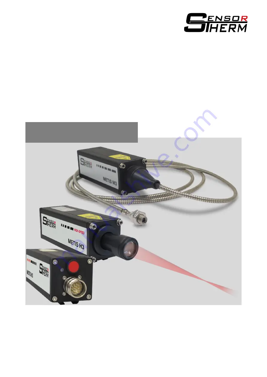
Pyrometers METIS M311 / M322 METIS H311 / H322
With 17-pin connector and PID controller
User Manual
Страница 1: ...Pyrometers METIS M311 M322 METIS H311 H322 With 17 pin connector and PID controller User Manual ...
Страница 2: ...1 3 Digital Inputs Outputs and Analog Input 10 4 1 4 Serial Interface RS232 RS485 M3 switchable RS232 RS485 H3 only RS485 11 4 1 4 1 Interface Converter Accessory 12 4 1 5 Shielding 12 4 1 6 Camera Module 12 5 Mechanical Installation 13 5 1 Mounting 13 5 2 Mounting Optical Fiber Optics optical fiber devices 13 5 2 1 Bending Radius Optical Fiber 13 5 2 2 Winding and Unwinding the Optical Fiber 13 5...
Страница 3: ...d Rate 24 6 13 Temperature Unit 24 6 14 Address 24 6 15 Interface Delay Answer Delay 24 7 SensorTools Software 25 7 1 Program Start Connecting the Pyrometer 25 7 2 Software Window 27 7 2 1 Main Window Graphs 27 7 2 2 Control Window 30 7 2 3 Device Settings and Configuration 32 7 2 3 1 Digital Input Output Configuration 33 7 2 3 2 Service functions 35 7 2 3 3 Interface 35 7 2 3 4 Data Collection Bu...
Страница 4: ...out of intended use Assignment of unskilled personnel Unauthorized modifications Technical modifications Usage of spare parts not approved The responsibilities of the delivery contract are valid as well as our general terms and conditions and terms of delivery and the valid statutory rule at date of the conclusion of contract 1 3 1 PID controller The PID controller has been designed to control tem...
Страница 5: ... device must have read and understood the operating man ual before beginning Operation and maintenance of the system is only to be performed by trained personnel This manual is to be kept and handed over when passed on 2 2 Supplementary Information about the Operation The following symbol is used to simplify the search for useful information NOTE This combination of symbol and signal word indicate...
Страница 6: ...he right The laser emits a visible red light with a maximum power of 1 mW and a wavelength around 650 nm SAFETY INSTRUCTIONS Never look into the direct or reflected laser beam Do not point the laser to anyone If laser radiation hits the eye the eye should be averted immediately 2 7 Through lens Sighting View Finder Devices with through lens sighting and temperature range above 1400 C are equipped ...
Страница 7: ...nder Laser targeting light push button Connector for TV signal 5 LED to indicate operating status 6 Connectors for power supply 2 linear analog current outputs for manipulated variable and actual value 4 digital inputs 2 digital outputs 1 analog input PID con troller a serial interface M3 RS232 RS485 switchable H3 RS485 7 Mounting rail 8 Mounting thread M5 for front mounting the pyrometer or acces...
Страница 8: ...een 3 Analog output 1 0 4 20 mA 4 Yellow 4 Analog output 1 0 4 20 mA 6 Blue 7 Analog output 2 0 4 20 mA 2 Red 8 Analog output 2 0 4 20 mA 9 Black 9 Digital input 1 1 7 Violet 10 Digital input 2 1 10 Pink 6 Digital input 3 1 5 Grey 5 Digital input 4 1 8 Brown green 14 Analog input 1 14 Grey pink 11 Digital output 1 1 11 Red blue 12 Digital output 2 1 12 White yellow 15 RS232 RxD RS485 B 2 15 White ...
Страница 9: ...f time 180 s Analog output 1 4 20 mA output temperature measured temperature Analog output 2 0 20 mA output temperature PID control output Digital input 1 Controller start stop Digital input 2 No function Digital input 3 Clearing of peak picker Digital input 4 Laser targeting light on off Analog input No function Digital output 1 Contact ready to use device ready to operate Digital output 2 Contro...
Страница 10: ...perature threshold is exceeded or falling below Exceeding the maximum allowed device tem perature Signal strength too low as dirty window alarm function enables to detect the degree of contamination of the pyrometer s optics viewing window or identify interferences dust in the IR sensor s sight path and trigger an alarm if necessary Controller activity of PID controller control process within adju...
Страница 11: ... limited by the cable length it is halved with each dou bling of the transmission path RS232 about 7 m cable length with 19 2 Bd Adjustable are values from 4 8 to 115 2 kBd RS485 about 2 km with 19 2 kBd Adjustable are values from 4 8 to 921 6 kBd Connecting one pyrometer via RS232 or RS485 In a short RS232 or RS485 connection to the mas ter computer receiving the data the pyrometer is connected d...
Страница 12: ... speed it is absolutely necessary to change the wait time in the ad vanced connection settings from 16 ms to 1 ms These settings are available in the Control Panel via the Device Manager Ports COM LPT USB Serial Port Port Settings Advanced Wait time More information is available in the FTDI application note AN_107 Advanced Driver Options 4 1 5 Shielding To meet the requirements for electromagnetic...
Страница 13: ...manufacturing tolerances the optical and mechanical axis are not running 100 in the same direction The pyrometer should be realigned if it is installed again and twisted in the same holder see 5 4 Alignment onto the Measuring Object 5 2 Mounting Optical Fiber Optics optical fiber devices 5 2 1 Bending Radius Optical Fiber The color code on the optical fiber identi fies the optic diameter and minim...
Страница 14: ...uide protective tube from the pyrometer s housing Pull the protective tube somewhat about the light guide on the colored side to avoid pulling it over the complete fiber after fiber assembly Remove the protective caps from the pyrometer and optical fiber insert the side with the turn pro tected fiber connector to the pyrometer and make sure that pin and recess snap together Tighten lock nut hand t...
Страница 15: ...ctors at two adjacent narrow band wavelengths and determine the temperature by forming the radiation ratio quotient In this method it is not necessary to know the emissivity of the target material It cancels out because the radiation ratio remains constant at a neutral attenuation of infrared radiation by dust smoke However this reduction will only be successful if signal attenuation occurs homoge...
Страница 16: ...software SensorTools see 7 2 2 Control window The targeting light will automatically switched off after 3 minutes if it is not switched off manually Adjustable via software under 7 2 3 Device Set tings Laser targeting light settings INFO The laser targeting light is turned off at a device temper ature above 65 C M3 devices or 60 C H3 devices If the targeting light does not turn on probably the dev...
Страница 17: ...he place of installation of the pyrometer should be checked excessive heat radiated from the measuring object When temperature falls below 55 C the camera module is working again 5 5 Setting the Measuring Focus Distance The focal distance is the distance at which the lens has the smallest spot size In most cases this dis tance is also the required measuring distance With focusable optics the focus...
Страница 18: ...of the spot size diameter outside the focused distance Measuring distances at manually focused optics are specified from lens front at motorized optics from the protection window 5 6 1 Manually Adjusted or Motorized Focus Optics Optics Model Temperature ranges C M322 300 1000 C H311 FSC 1500 C H322 FSC 1200 C M311 M322 all other temp ranges H311 FSC 1500 C H322 FSC 1200 C Meas distance a mm Optics...
Страница 19: ...re 5 6 3 Calculation of the Spot Size Diameter outside the Focused Distance The spot size diameter determines the area on the measurement object from which 90 of the temper ature radiation is detected by the pyrometer therefor the spot size tables specify spot sizes for different measuring distances or focused distances For calculating intermediate values in front of and behind the focused measuri...
Страница 20: ...n nels in the required measuring range run uniformly par allel so the ratio is constant If the temperature values of the curves are identical at the same emissivity setting then the emissivity slope is 1 Do they run parallel so the correct value for the emissivity ratio must be found such by comparative measurement with a thermocouple and subsequent ratio setting until the temperatures match 6 2 E...
Страница 21: ...0 9 Titanium shiny 0 35 0 45 0 3 0 4 Titanium oxidized 0 55 0 85 0 55 0 85 Tungsten shiny 0 3 0 4 0 3 0 4 Tungsten oxidized 0 7 0 9 0 7 0 85 Brick 0 85 0 9 0 8 0 9 Zinc 0 45 0 58 0 45 0 55 Measurement deviations at a 10 false set emissivity at a temperature of 700 C 10 6 5 C 10 5 C 10 7 C 11 5 C 6 3 Transmittance Is a viewing window located between measuring object and pyrometer the transmittance ...
Страница 22: ...he inertial measurement 6 6 1 Dynamic Adaptation at Low Signal Levels only M3 At the beginning of the temperature range at high measurement speeds the risk of measurement un certainty is given by signal noise This is compensated by the pyrometer by automatically increasing the response time at the beginning of the temperature range from 1 ms to 4 8 and finally 16 ms 6 7 Maximum Value Storage Peak ...
Страница 23: ... separately Depending on the connected devices to 0 20 mA or 4 20 mA Analog output 1 always provides the measured temperature always the temperature displayed in the control window in SensorTools see 7 2 2 Control window Note With older firmware versions the same settings are possible as at analog output 2 A firmware update to the latest version eliminates this possibility and prevents that the ou...
Страница 24: ...r Delay During operation of the pyrometer via RS485 it may happen that the connection is not fast enough to detect the response of pyrometer time to a command from the master e g because the line is still busy with sending before receiving This sometimes occurs in older PCs or interface adapters or by slow switching times of interface adapters and manifests itself in transmission errors of interfa...
Страница 25: ...lways to install the latest software and firmware available on the home page in the download area under www sensortherm de en download section In SensorTools in the Communication Options tab it can be checked to a new software ver sion 7 1 Program Start Connecting the Pyrometer When the software is started the device over view opens in this case up to 4 pyrometers can be connected to the software ...
Страница 26: ...e following settings can also be accessed from the Device configuration but can be found here again for quick access The data collection settings control the transmission of measured data from the py rometer to the PC also see 7 2 3 4 Service functions are used to back up print or restore device parameters or create service files for remote diagnostics in the event of a problem see 7 2 3 2 Interfa...
Страница 27: ...dow in the main window shows the temperature profile in time Scale X Axis allows to set the time at which the graphs window is filled with measured values If the time is changed in Scale X Axis the graph is rebuild from the center of the window rebuilds the graph from the left Switches the X axis of the graph between time and a stopwatch where with press ing the displayed time can be set to 0 at t...
Страница 28: ... channel mode with status in formation must be selected For displaying of the setpoint of the PID controller the multi channel mode with status information should preferably be selected The transferred measured value data can be recorded on hard disk for subsequent analysis Click on the recording button to start and stop recording the button flashes when the re cording is active Pause interrupts t...
Страница 29: ... with a PID controller Stops recording when a control process is stopped even with automatic or external stop error etc Inactive I O port Stops recording when a digital input or output is disabled Post record of recording recording can be continued for a while if control process is stopped e g to record a cool down process Maximum data sets in memory Number of measurement data sets consists of mea...
Страница 30: ...witches on and off the peak picker and allows clear settings for the activated peak picker Measurement parameters The displayed measuring parameter depends on the measuring mode In case of ratio temperature measurements the emissivity slope can be set see 6 1 in the case of 1 channel measurements the emissivity input field is available first The setting field can be expanded to display the measure...
Страница 31: ...nding on the measuring mode the emissivity or the emissivity slope Test picture Shows a test image instead of the camera picture Miscellaneous Date time format US American time format month day year DE German time format day month year Image system PAL 720 x 576 Pixel NTSC 720 x 480 Pixel Color mode Color or black and white Device time device date Time and date by the pyrometer Setup clock Transfe...
Страница 32: ...ngs only devices with laser targeting light Time until a laser targeting light switches off automatically 2 Analog outputs are available 0 20 mA or 4 20 mA sets the output current according to the requirements To test the func tionality of each analog out put By moving the slider or by entering a value the corre sponding current is set to the output The output is only activated when the hook on is...
Страница 33: ...he controller otherwise would recognize a cold oven and heat up fully and possibly burn out the oven 7 2 3 1 Digital Input Output Configuration Each digital input and output can be assigned a function also see 4 1 3 Digital Inputs Outputs Digital Inputs activated by voltage pulse or a voltage of 24 V No function A switching signal at the input has no effect External clearing Resets the peak value ...
Страница 34: ... within the temperature has to be The output is activated if the measured value is outside the defined value Controller active Output is active when the controller is active Successful control Output is active when a control process is terminated a possibly hold time has elapsed Various settings Switching value Activates the corresponding output at the set switching value the LEDs 1 3 on the unit ...
Страница 35: ...ered in C or F Changing the mode will not change the entered values no conversion will be done 7 2 3 2 Service functions To back up for printing or restore device pa rameters or create service files for remote diagnosis of problems Create configuration file A configuration file includes all device settings made by user This can be used e g to setup a new py rometer with the same values and setting...
Страница 36: ...ransmitted infor mation can be selected The se lection affects the speed Single measured value fastest Saves and transmits the temperature value shown on the display Is used with M3 and H3 models together with the buffer mode at 921 6 kBd to ensure error free high speed communication Multi channel mode Transmits the temperatures of all channels simultaneous ly and displays them in the software Wit...
Страница 37: ...ding settings 7 2 3 5 Single Point Adjustment The single point adjustment function is used to readjust the pyrometer to a mainly used measuring temperature The function can be used e g to compensate optical losses in measurements through windows or lenses with unknown transmittance for example when coupling the pyrometer into a laser beam deliv ery system For this purpose the pyrometer has to be a...
Страница 38: ...ocess takes between one and two minutes If anything goes wrong for example the calibration source does not work smoothly nevertheless calibration val ues are written into the pyrometer In this case the process should be performed again or the device should be reset to factory settings this sets all calibration values back to factory calibration Load adjustment value file loads adjustment values fr...
Страница 39: ...tory setting assignment can be changed in the pyrometer port settings see 0 Parame ters Settings and 7 2 3 Device Settings and Configuration An integrated PID controller is auto matically detected by the software and activates the button for the controller configuration A setpoint and the necessary PID control parameters are entered directly in the software and transferred to the py rometer by pre...
Страница 40: ...ry selected setpoint limit output see 4 1 3 Digital Inputs Outputs and under 7 2 3 Digital Input Output if set temperature is exceeded or falls below The required temperature has to be set relative to the setpoint temperature in the control parame ter field not as absolute value Setpoint deviation defines the maximum permissible deviation between setpoint and actual val ue Used to detect if a ramp...
Страница 41: ...o be used see under 7 2 2 Control window Digital Input Output The parameters for the selected setup can be entered directly in this window using the keyboard with Enter or the Tab key they are transferred to the pyrometer Setups can be saved individually or as a complete list to the PC and loaded from there Caution With an active Setup the pyrometer operates using the setup values All the adjustme...
Страница 42: ...iew a detail To select details a selection can be dragged with the mouse To move the view on the temperature or time scale the view can be moved with the mouse middle of the scale or the upper and lower limits are changed upper or lower end of the scale Color settings of graphs same as in main windows Recorded data Current mouse position File information of the vertical mouse position View the com...
Страница 43: ...Subsequently the software SensorFlash is opened see 8 Via this software the pyrometer must be connected the flash file must be selected and the flash operation can be performed Firmware Update IF RD RF is used to update the PID program controller Regulus RD or RF or the digital display IF0000 Software version Clicking on Please check checks whether a SensorTools update is available If a newer vers...
Страница 44: ...th and press Connect The grey status bar shows your device if connected Click Open Flashfile to select and open a new firmware file Select the new and suit able BIN file with a dou ble click or with Open SensorTools firmware path C Program Files x86 Sensortherm GmbH SensorTools Firm ware Now the button Flash is available press it to start the upgrade process Confirm the safety note Important Do no...
Страница 45: ...l focusable or optional motorized focus or fixed focus optics Power consumption max 6 VA all outputs unconnected Ambient temperature 0 80 C 32 to 176 F fiber optic and optics on optics side 20 to 250 C 4 to 482 F Note To prevent its overheating the laser targeting light is deactivated at a device temperature from 60 C the camera module from 55 C Device specific H3 Model H311 H322 Temperature range...
Страница 46: ...eset or external clear via digital input Parameter settings Via serial interface PC software SensorTools or via self compiled communication program Slope ratio switch off limit for measurement switch off limit for dirty window alarm emissivity transmission fill factor temperature sub range settings for max value storage device address baud rate response time selecting analog outputs 0 4 20 mA inte...
Страница 47: ...METIS M311 M322 H311 H322 17 pin Technical Data 47 9 2 Dimensions The case dimensions are the same for all models and differ in the mounting parts ...
Страница 48: ...geting light 2 View finder 4 TV color camera 14 Serial interface 2 RS485 5 RS232 RS485 switchable 15 Lens type 1 Fixed focus optics 2 Focusable optics 3 Fiber optic cable 0 2 mm Ø with focusable optics 4 Fiber optic cable 0 4 mm Ø with focusable optics 8 Motorized focus B Heavy duty stainless steel sensor head for 0 2 mm fiber with OQ25 C Heavy duty stainless steel sensor head for 0 4 mm fiber wit...
Страница 49: ... bench top model Regulus RF PID program controller for panel mounting KG14 00 Aluminum cooling jacket KG20 00 Cooling plate for devices with focusable optics KG31 00 Cooling cap for devices with focusable optics BL10 00 Air purge accessory for devices with fixed focus optics BL11 00 Air purge accessory for devices with focusable lens BL13 00 Air purge accessory for fibre optic cable lens assembly ...
Страница 50: ...nally adjust at Sensortherm Fiber optic pyrometers must always be calibrated together with the associated optics and the optical fiber cable A recalibration is also necessary if for fiber optic pyrometers the optics OQ12 is replaced by OQ25 or vice versa and or a new fiber optic cable should be used 10 3 Trouble Shooting A device malfunction is indicated by a red power status LED This may be a dat...
Страница 51: ...al programs with device address 00 Input in terminal program of SensorTools without device address 00ar1 CR sets the 2nd analog output to 4 20 mA 00ar reads out how the analog output is set ar1 CR sets the 2nd analog output to 4 20 mA ar reads out how the analog output is set Note The following commands are valid with the newest firmware version Command Parameter Description Settings aa aaX XY Out...
Страница 52: ...corresponds 5 120 in 0 1 steps eg0 emissivity slope 0800 1200 0x0320 04b0 eg1 emissivity slope channel 1 0050 1200 0x0032 04b0 eg2 emissivity slope channel 2 0050 1200 0x0032 04b0 et XXXXXX Response time in steps of 100 µs XXXXXX 0x000000 0186A0 corresponds 0 10 s fh X Celsius Fahrenheit selection X 0 1 0 Celsius 1 Fahrenheit ff XYYYY Spot size fill factor X 1 2 YYYY 0050 1000 corresponds 5 100 in...
Страница 53: ...puts digital output X X 1 2 YY 00 ff YY 00 no output YY 04 Signal strength contact YY 08 Setpoint band YY 01 device ready contact YY 05 Over temperature YY 09 Controller active YY 02 Material contact YY 06 Setpoint limit 1 YY 0A Control successful YY 03 limit switch contact YY 07 Setpoint limit 2 pia XXXX Automatic targeting light shutdown XXXX 0x0000 ffff 0 65535 s X 0 targeting light never turns...
Страница 54: ...nt Ti in sampling times XXXXXX 0x000000 00ffff xa XXXX Sampling time in 10 µs steps M3 XXXX 0x0064 09C4 1 ms 25 ms H3 XXXX 0x000A 09C4 0 1 ms 25 ms xb XXXX Setpoint deviation in 1 10 Grad xl XXXX P dynamic XXXX 0x0000 2710 0 01 100 00 0 01 steps xp XXXX Proportional band Xp XXXX 0x0000 2710 0 1 1000 0 0 1 steps ym XXXX Minimum control output power Pmin XXXX 0x0000 03E7 0 0 99 9 0 1 steps ys XXXX P...
Страница 55: ... NTSC 1 PAL vq X Image setting color monochrome X 0 1 0 color picture 1 monochrome image vt vm X Test image X 0 1 0 Normal image 1 Test image In addition for devices with built in motorized focus moa XXXX Measuring distance XXXX in mm is possibly rounded up or down in 10 mm resolution Old commands to standardize the command structure some old commands with numeric parameters are replaced with new ...
Страница 56: ...rface commands 51 Interface converter accessory 12 Interface delay 24 Interface type 24 M Main window data recording 27 Maintenance 50 Maximum value storage clear time tCL 22 Mechanical installation 13 Model designs 7 Mounting 13 Mounting optical fiber optics 13 P PID controller 39 Power supply 8 Program start connecting the pyrometer 25 Pyrometer calibration 50 Pyrometer Parameters Settings 20 R ...
Страница 57: ...METIS M311 M322 H311 H322 17 pin Index 57 ...
Страница 58: ...rtherm GmbH Hauptstraße 123 65843 Sulzbach Tel 49 0 6196 64065 80 Fax 49 0 6196 64065 89 E Mail info sensortherm com Internet www sensortherm com Sensortherm GmbH Metis_M311_M322_H311_H322_17 pin Jan 29 2019 ...