July 2017 Form 8150A
www.sencore.com | 1.605.978.4600
Revision 1.1
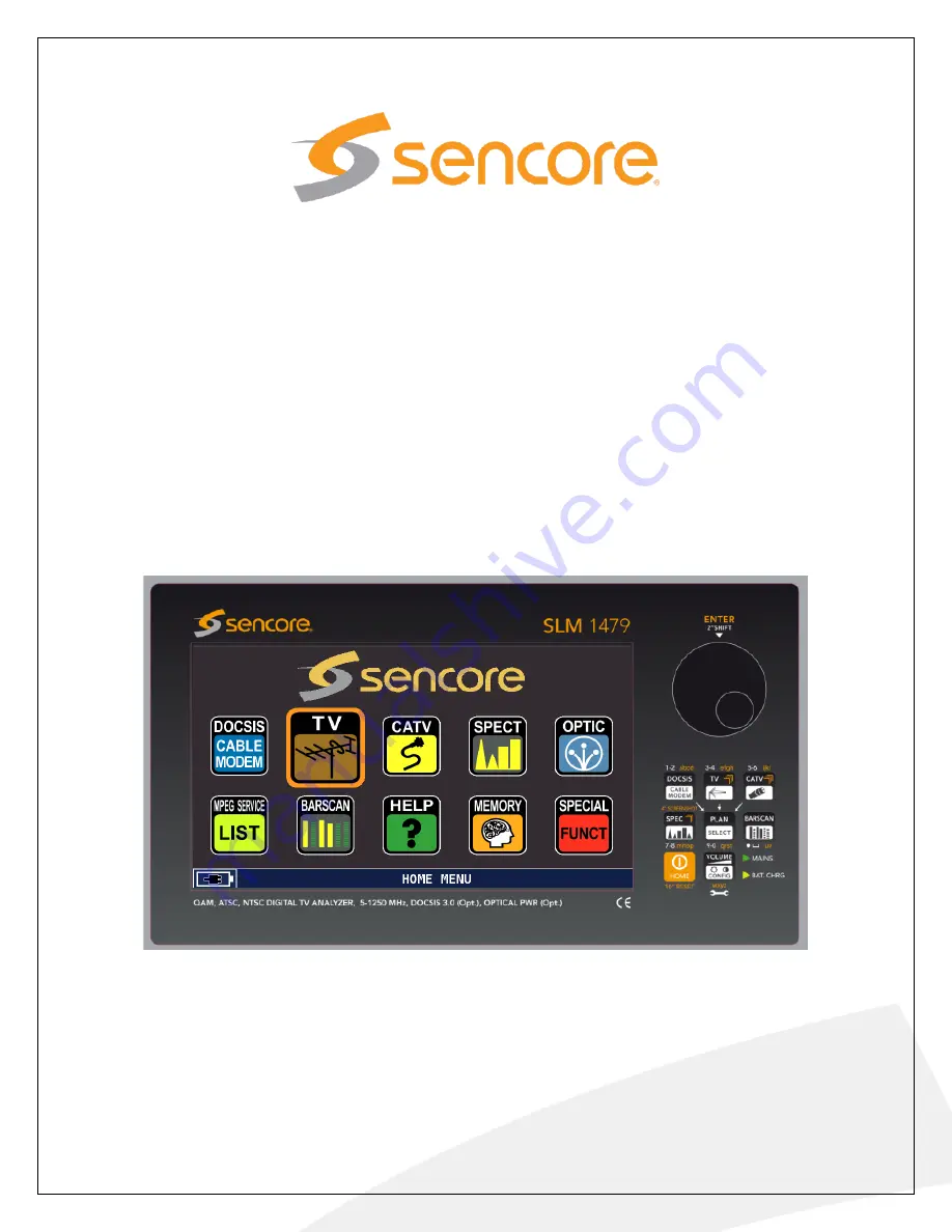
SLM 1479
CATV, TV,
Signal Level Meter
User Manual
Страница 1: ...July 2017 Form 8150A www sencore com 1 605 978 4600 Revision 1 1 SLM 1479 CATV TV Signal Level Meter User Manual...
Страница 2: ...ty web pages that are beyond the control of Sencore The presence of such links does not imply that Sencore endorses or recommends the content on those pages Sencore acknowledges the use of third party...
Страница 3: ...SLM 1479 User Manual Page 3 124 Revision History Date Version Description Author 05 26 2016 1 0 Operations Manual for SLM 1479 GK 07 13 2017 1 1 Small edits SV...
Страница 4: ...CISE 17 2 3 DROPDOWN MENU SELECTIONS 18 2 4 MEASUREMENT SIGNAL SELECTION 19 2 5 METER TUNING 19 2 6 QUICK START MEASUREMENTS 20 2 7 ENTERING FIELD VALUES 21 2 8 TOUCH SCREEN SHORTCUTS 21 SECTION 3 MET...
Страница 5: ...83 RECALL DATALOGGER View TV Data Log File 56 5 84 MANUMEMORY Creating or Editing TV Channel Plans 57 5 85 TV FILE MANAGER Renaming or Deleting Files 59 5 9 TV HELP SIGNAL DISCOVERY 60 5 10 TV BAR SC...
Страница 6: ...EAM GENERATOR 102 SECTION 8 OPTIC POWER MEASUREMENTS 105 8 1 OPTIC POWER FUNCTION 105 8 2 OPTICAL INPUT CONNECTORS 106 THE OPTICAL OPTION ON THE SLM 1479 IS SUPPLIED WITH SEVERAL FIBER CABLE ADAPTERS...
Страница 7: ...d video is displayed providing advanced signal analyzing The SLM 1479 further provides a full arsenal of unique special tests and control features to assist technicians in troubleshooting cable and TV...
Страница 8: ...tions custom channel plan programming meter cloning logger file download and export in xls firmware updates and more Please read the SMART Users Guide supplied on the CD with the instrument for inform...
Страница 9: ...c 3 4 ijkl letters E Control Wheel Enter Pushbutton Rotate Increments field selection on the display Push ENTER button to enter a field for test or selection F CATV Pushbutton Selects Cable Measuremen...
Страница 10: ...for interface with PC for file upload firmware updates Use with SMART software via USB connection C USB A Connector Port for USB memory stick stores screen shots logs captures etc Used to read write...
Страница 11: ...nu Icon Familiarization The Home Menu of the SLM 1479 is the first menu you see when powering on the meter You may return to this menu from any other menu by briefly pressing the HOME pushbutton The H...
Страница 12: ...elected satellite broadcast TV or cable TV measurement mode G MEMORY Touch to manage logger files start channel logs or recall log files H HELP Touch for tuning assistance Auto Discovery to determine...
Страница 13: ...ower supply adapter which strictly meets all technical specifications and industry safety CE UL etc requirements 1 7 Battery Charging Management The latest battery technology hyper lithium polymer Li...
Страница 14: ...not used Recharge the battery every 3 4 months when not used or in storage NOTE Do not leave the battery in a discharged state If stored or not used periodically charge the battery Battery operating t...
Страница 15: ...damage its protective wrap Replacement You need to be absolutely sure you have the proper replacement Li Po battery pack for your SLM 1479 Sensing wires to the battery pack are critical in battery ch...
Страница 16: ...us to the screen at locations of a listing heading field or an icon This selects the test or field The selected field is indicated by a colored box typically red or dark orange The color depends on th...
Страница 17: ...ighlight disappears The center colored area is now active and the yellow box indicates the selected listing 5 Select a CATV tuning plan center colored area touch your finger to the screen listing seve...
Страница 18: ...list The list immediately updates with the entered channel number centered in the list To select the desired channel touch the listing with your finger tip or stylus Frequency Selection Entry The FRE...
Страница 19: ...he available testing features measurements screen configurations spectrum analyzer screen configurations and features special test selections signal channel plans and individual screen popup menus The...
Страница 20: ...ructions Continued a BROADCAST TV b CABLE Follow a b c instructions below relative to the signal type selected above 3 Select a tuning channel plan and plan variation in the PLAN SELECTION MENU Press...
Страница 21: ...are selected select or touch the ENTER field to apply the value 2 8 Touch Screen Shortcuts The touch screen provides selections or shortcuts to move to other measurement pages simply by touching area...
Страница 22: ...SCAN MPEG SERVICE LIST FUNCT MEAS CATV SPEC TV SAT SPECIAL HELP MEMORY BAR SCAN MPEG SERVICE LIST FUNCT MEAS CATV SPEC TV SAT Main Measurement Page to Full Screen Video Monitor When in the main measu...
Страница 23: ...y touch the screen with your finger over the listing Alternatively you may push the ENTER pushbutton and slide your finger over the arrow section of the Control Knob to navigate to other listings The...
Страница 24: ...audio circuits for monitoring Selecting this mode defeats the normal RF measurement functions Note that the normal default of the VIDEO IN setting is INT which provides normal meter use and video view...
Страница 25: ...ntrol to either turn ON or turn OFF the battery saving features of the meter The SLM 1479 provides two battery saving features When the BATTERY SAVING setting is in the ON mode if no user key press or...
Страница 26: ...ER INFO and DIAGNOSTIC listings Each listing has an associated configuration menu Touch the screen listing to select the desired configuration menu This section of the manual covers each of the CONFIG...
Страница 27: ...sound from the meter s speakers when touch commands are received by the meter The settings include OFF LOW MEDIUM and HIGH selections The OFF selection disables the touch beeps The LOW MEDIUM and HIG...
Страница 28: ...ing this field to DISABLE will cause the touchscreen to be unresponsive to any touch selection Setting this field to ENABLE permits touchscreen sensitive display selection Note Full user control is po...
Страница 29: ...eway address entries To configure a LAN connection navigate to the CONFIGURATION MENU and touch the METER field 22 TV Configuration The TV listing provides settings relative to the terrestrial TV meas...
Страница 30: ...ed to measure the SNR The measurement is calculated using a single scan line of the detected video modulation of the selected channel The SNR LINE field provides selection of the analog channel video...
Страница 31: ...may be used to offset the frequency of the channel selected or define a test frequency 3 23 2 TEST SETTINGS The TEST settings select or define the input receive RX level for the cable system CMTS Thi...
Страница 32: ...cting the lower frequency from the larger frequency Note If the LNB L O frequency is not the default 0 MHz the frequency readout in the meter s measurement screen will indicate improperly for the know...
Страница 33: ...sor program version and serial number The menu further indicates the inclusion of optional hardware and firmware features The MAC address of the meter is also indicated The Meter Info Menu contains an...
Страница 34: ...test of the meters internal circuits The circuits should all indicate OK if they are working and responding to the microcontroller If a listing does not indicate OK a likely problem exists Please cont...
Страница 35: ...phono connector Connect an RCA phono to RCA phono connection cable from the composite video source to the VIDEO IN connector of the meter Select the VOL CONFIG or Quick View menu by touching the VOL...
Страница 36: ...listing provides a suitable channel plan which includes all the off air TV channels from 2 to 69 AUTOMEMORYtv This selection provides a list of channel plans to choose from that are AUTO plans These...
Страница 37: ...bes the fields of a digital channel measurement as numbered in the figure below MEAS 15 aBER 10 9 ERR 0059 2 3 4 5 6 7 8 POWER 5 dBmV MER 29 9 dB 8 12 16 20 24 28 32 36 40 42 QLTY PASS Ns MAR 11 5 dB...
Страница 38: ...or network Identification numbers 16 aBER Bit Error Ratio measurement after error correction measurement 17 bBER Bit Error Ratio measurement before error correction 18 Noise Margin Ns MAR Provided ma...
Страница 39: ...vertical blanking interval Be sure to select a line in which there is no test signal or data signals such as close captioning The default Line Num is selected in the meter s configuration menu Please...
Страница 40: ...garding the MPEG transport stream and the selected video service program contained in the stream The top and bottom fields are the same as listed and described in the Main Measurement page in section...
Страница 41: ...to match the modulation type and the number of symbols in the RF transmission When measuring an 8VSB transmission the constellation diagram consists of 8 vertical spaced sections with detected symbol...
Страница 42: ...e video resolution aspect ratio and MPEG compression level The audio information includes the format and data rate After a few seconds for review the bottom section is pushed to the bottom of the disp...
Страница 43: ...e CHANNEL LOGGER Monitors and charts the digital RF measurements of a TV or cable channel 5 43 VISUAL NIT The SLM 1479 provides an information page of the data found in a DVB compliant signal s NIT Ne...
Страница 44: ...nd packet errors yellow Menu when in the The channel monitor provides a continuous graphing of the satellite transponder being received Bottom Chart The bottom chart provides charted values of the cha...
Страница 45: ...USB field and increment to ON Press the ENTER selection or press the large control knob in to Enter Measurements are active and the bottom of the display indicates SAVING DATA ON FILE PRESS ENTER TO S...
Страница 46: ...wer level 4 Marker Frequency The frequency represented by the location of the vertical red marker line on the spectrum analyzer display A selectable field permits moving the marker line The marker may...
Страница 47: ...ncy locations At the center bottom of the spectrum analyzer display is added a Delta Marker Power Delta MRK P measurement which indicates the level difference between the red and white frequency locat...
Страница 48: ...dth The bottom center field in the spectrum analyzer display indicates the power measurement in the selected bandwidth 5 63 Spectrum Analyzer Delta Marker Measurement The Spectrum Analyzer includes a...
Страница 49: ...ZZER NOISE MARGIN GRAPH TEST The BUZZER NOISE MARGIN GRAPH test abbreviated BUZZ NOIS MAR GR is a special function which provides a time charted graph of the Noise Margin measurement of a selected sat...
Страница 50: ...signal lock The received signal performance noise margin is graphed from left to right scrolling a 7 second window of performance Each horizontal increment represents a 1 second time interval Interrup...
Страница 51: ...at the right of the display Then touch the ATTENUATION TEST field which takes you directly to the test function The test function is highly automated with three preselected test frequencies Connect th...
Страница 52: ...nd records performance measurements to a log file The scanning progress and test summary is shown during the scanning RECALL DATALOGGER Selects and recalls a previously scanned and stored log file by...
Страница 53: ...uration box are listed and explained below FROM PLAN Selects the master tuning plan to use for scanning for channels Use USABRO for scanning broadcast TV channels in North America TO FILE N Selects th...
Страница 54: ...te when all the channels have been scanned 7 Touch the Exit field to exit the scan The Auto scanned plan is automatically selected for use by the meter The plan is then available for use 5 82 SAVE DAT...
Страница 55: ...Starts the logging saving channel performance testing data to the Data File name in the Date File field AVAILABLE LOGGER 99 Indicates the available memory locations for storing logging data files To...
Страница 56: ...Knob to increment through the available log files Press the RECALL field to view the file s measurement contents The DATALOGGER viewer shows the file name and point number in the upper left to identi...
Страница 57: ...ture permits edits or changes to listed channels within a previously created manual MANU channel plan The following sections provide information on creating and editing a MANU channel plan To Manually...
Страница 58: ...elow the currently highlighted field DELETE ITEM Deletes the highlighted listing from the selected plan RETURN Returns to previous menu To Edit an Existing Plan 1 To make changes or additions to an ex...
Страница 59: ...the AUTOMEMORY feature or with a MANUMEMORY feature of the meter These files are typically named AUTO 1 AUTO 2 etc or MANU 1 MAN 2 etc by the meter However these file names can be changed to a more re...
Страница 60: ...tal signal or detecting an analog signal within the channel The boxes on the right in the center list the modulation frequency and symbol rates as discovered by the meter When the search is completed...
Страница 61: ...number of channels or bars displayed in the bar chart A yellow bar represents a digital signal channel while a solid blue bar represents an analog signal channel The marker a vertical red dotted line...
Страница 62: ...DOWN arrow pushbuttons to move the marker to the desired channel or bar 5 MRK FREQ Marker Frequency The Bar Scan display or span is centered upon a selected channel shown in the field under the MRK C...
Страница 63: ...rovides a suitable channel plan which includes all the CATV channels from 2 to 158 AUTOMEMORYtv This selection provides a list of channel plans to choose from that are AUTO plans These plans are creat...
Страница 64: ...and measurement pages The following section describes the fields as numbered in the nearby figure 6 21 Main Digital Measurement Page Description aBER 10 9 ERR 00 2 3 4 5 6 7 8 POWER 1 5 dBmV MER 31 9...
Страница 65: ...ained in MPEG 9 ANNEX The standard signal type or reference J83B for CATV digital signals 10 SYM RATE The symbol rate of the RF digital carrier in million MEGA symbols per second QAM 256 uses a standa...
Страница 66: ...a basic spectrum analyzer view Any voltage input to the RF jack is indicated by the voltmeter measurement The 2nd page provides a waveform monitor screen in which the signal to noise ratio and hum is...
Страница 67: ...the horizontal sync period to the beginning of the next sync period The waveform monitor offers a LINE ZOOM feature in which the first part of the scan line can be expanded for viewing Select the WAVE...
Страница 68: ...of the detected RF symbol accuracy The constellation diagram changes its appearance to match the number of symbols in the QAM RF signal For example a QAM 64 signal has 64 squares while a QAM256 signa...
Страница 69: ...ent page provides information regarding the MPEG transport stream and the selected video service program contained in the stream The top and bottom fields are the same as listed and described in the M...
Страница 70: ...a full video display you may return to the previous measurement screen by touching the center of the screen 6 4 CATV MEASUREMENT POPUP MENU The CATV measurement page includes a popup menu that provid...
Страница 71: ...The SLM 1479 provides an information page of the data found in a DVB signal s NIT Network Information Table To view the NIT information touch the MENU field and touch the VISUALIZE NIT listing Press t...
Страница 72: ...ket errors yellow Menu when in the The channel monitor provides a continuous graphing of the satellite transponder being received Bottom Chart The bottom chart provides charted values of the channel s...
Страница 73: ...nd enter a file name for the data to be stored on the USB stick Select the SEND TO USB field and increment to ON Press the ENTER selection or press the large control knob in to Enter Measurements are...
Страница 74: ...ode Selectable field permits digital or analog selection 3 Reference Power Indicates the level of the top line of the spectrum analyzer commonly called the reference power level 4 Marker Frequency The...
Страница 75: ...ide two adjustable frequency locations At the center bottom of the spectrum analyzer display is added a Delta Marker Power Delta MRK P measurement which indicates the level difference between the red...
Страница 76: ...Bandwidth Measurement The Spectrum Analyzer includes a marker bandwidth MRK BW measurement This measurement provides a means to select a bandwidth of interest for a level measurement The bandwidth is...
Страница 77: ...system Elevated leakage levels indicate a shielding problem which should be corrected INGRESS Shows the potential ingress interference problems in the upstream cable spectrum by providing a spectrum a...
Страница 78: ...ttings select a test frequency in the range of 100 150 MHz to match the leakage test transmitter frequency and provide compensation for the antenna antenna factors and distance Area The Area setting a...
Страница 79: ...e SPEC FUNCT icon with the CATV icon highlighted to access the CATV Special Functions Menu Touch the LEAKGE listing or field to advance to the Leakage Setup Menu After appropriate setup selections tou...
Страница 80: ...relevant measurement unit A horizontal dotted line shows the real time signal level value at the current marker position current frequency value REF PWR Reference Value With the Standard Navigation Mo...
Страница 81: ...easurements in the BUZZ NOISE MAR GR function include the following NOISE MARG The Current Noise Margin measurement MAX N MARG Maximum or best Noise Margin measurement since the test began signal lock...
Страница 82: ...ng the test results MANUMEMORY Provides creation and editing of manually created transponder channel plans FILE MANAGER Provides selection of logger and satellite manual created channel plans for rena...
Страница 83: ...el prior to adding it to the channel plan POWER This defines the minimum signal level of a digital channel during the channel scan required to consider the digital signal a valid channel DISCOVERY Thi...
Страница 84: ...meter or may be written to a file on the USB memory stick The file is named for latter recall and test result viewing To begin a data logger capture select the SAVE DATALOGGER by touching the MEMORY i...
Страница 85: ...l plan a LOGGER FUNCTION screen shows the scanning logging progress A Total Test Report section on the right of the display screen indicates the progress of the scan and summarizes the performance of...
Страница 86: ...rement through the available log files Press the RECALL field to view the file s measurement contents The DATALOGGER viewer shows the file name and point number in the upper left to identify the logge...
Страница 87: ...ature permits edits or changes to listed channels within a previously created manual MANU channel plan The following sections provide information on creating and editing a MANU channel plan To Manuall...
Страница 88: ...below the currently highlighted field DELETE ITEM Deletes the highlighted listing from the selected plan EXIT Returns to previous menu To Edit an Existing Plan 1 To make changes or additions to an exi...
Страница 89: ...OMEMORY feature or with a MANUMEMORY feature of the meter These are channel plan files and are typically named AUTO 1 AUTO 2 etc or MANU 1 MAN 2 etc by the meter However these file names can be change...
Страница 90: ...h it The HELP icon is located within the Spectrum Analyzer s popup menu When in the Spectrum analyzer touch the MENU field at the bottom right of the screen Touch the HELP icon If the channel spectrum...
Страница 91: ...chart The number of channels plotted in the bar chart is determined by the selected span SPAN For a CATV Bar Scan measurement touch the BAR SCAN icon with the CATV icon highlighted The following secti...
Страница 92: ...he CHAN header The CHAN field is selectable and the channel value may be changed Changing the value moves the red cursor or marker on the display Highlight the CHAN field and use the UP and DOWN arrow...
Страница 93: ...r REF PWR The reference value establishes the dBmV level of the top horizontal bar of the bar graph This field may be changed by red highlighting the field and pressing the UP and DOWN arrow pushbutto...
Страница 94: ...nt sections provide detailed informaiton on the DOCSIS measurements SETTINGS MODEM SETUP The SETTINGS menu provides sections and fields used to configure the internal MODEM for system testing The sett...
Страница 95: ...gnal to evaluate reverse signal path attenuation or signal performance The generator provides a QAM test signal with selectable types and variable output level to insure flexibility in troubleshooting...
Страница 96: ...SEARCH Ranging Method There are two method used by the SLM 1479 to search for a downstream DOCSIS channel s The SEARCH selection may be set to AUTOMATIC or FIXED Touch or Highlight the SEARCH field a...
Страница 97: ...t results for the US channel For example if the CMTS responds to an Upstream signal at 5 dBmV from the SLM 1479 s modem outputting 40dBmV then the upstream attenuation is 45dB ATT 45 dB REG MODE The R...
Страница 98: ...g the DOCSIS MEASUREMENTs requires proper setup of the modem and CMTS address Please perfrom MODEM SETUP and ADDRESS CONFIG prior to performing the DOCSIS MEASUREMENTS as explained in the previous sec...
Страница 99: ...ream US channels are established and test measurements completed Additional PING REPORT and IP CONFIGURATION measurement sections and data is provided Progress or steps within the automatic DOCSIS tes...
Страница 100: ...tion constellation of the downstream DOCSIS channel SR Symbol Rate of the downstream DOCSIS channel Pow Channel Average Power of the downstream DOCSIS channel MER Modulation Error Ratio measurement of...
Страница 101: ...umber of lost packets LOST the present Packet Error Ratio PER and the minimum LATmin maximum LATmax and average AVG latency time of the various sent and received packets TX PKG Transmit packets during...
Страница 102: ...TONE PILOT 1 and Upstream Generator 2 TONE PILOT 2 The RF outputs of the Upstream Generator s are produced by the SLM 1479 s internal RF cable modem The RF modem output is at the top right side of the...
Страница 103: ...rrow pushbuttons Select the Upstream Generator Symbol Rate The Symbol Rate of the upstream digital signal may be selected including 160 320 640 1280 2560 5120 kS s rates Select the SYM RATE field by p...
Страница 104: ...lecting Generator 2 A second Upstream Generator is available to provide a second alternating RF upstream output signal The second generator becomes available when the TOGGLE field is set to Enable Bot...
Страница 105: ...AL IN connector using one of the available adapters Several adapters are provided to make connection to popular fiber connector types See the next section 8 2 of this manual From the Home Menu touch t...
Страница 106: ...pe Adapter provides an optical connection from the common ST or Straight Tip type fiber connector The female receptacle accepts connection from a male end ST type fiber connector The SLM1478 is shippe...
Страница 107: ...el plans and configuration settings of the meter USB Memory Stick Insertion To transfer files to or from a USB memory device the memory stick must be inserted into the USB A receptacle located on the...
Страница 108: ...b to highlight the UPGRADE MEM PLAN field and press the knob to select In the MEMORY PLANS menu touch the LOAD MEMORY PLANS FROM USB KEY A warning message menu appears as shown below indicating that a...
Страница 109: ...ADE MEM PLAN field and press the knob to select In the MEMORY PLANS menu touch the SAVE MEMORY PLANS ON USB KEY A message appears as shown below indicating that a mem plan save will replace an SLM1479...
Страница 110: ...SPEC pushbutton on the front panel for a minimum of 10 seconds This initiates a second function of this pushbutton which provides a display screen shot capture You will hear an audible beep from the...
Страница 111: ...nd zoom Custom Channel Plans 25 199 Ch per plan DIGITAL CATV TV SPECIAL FUNCTIONS AutoDiscovery Automatic Digital Signal Type ID Antenna Reception Peaking Buzz Noise Margin Graph Attenuation Test Atte...
Страница 112: ...ure or Envelope MENU Selectable Trace color schemes Customizable GREEN BLUE GREY BROWN configuration menu selection MPEG Service List Function Network Program Bouquet ID Service Names Listed Modulatio...
Страница 113: ...e Selectable color themes green blue grey brown Operation Dual command TOUCH and or MECHANICAL Control Pushbuttons 24 step encoder 8 button mechanical switch panel Operating temperature range 0 C to 5...
Страница 114: ...re per the FCC designations Sub Band VHF Cable TV Channels 5 50 Mhz Low High VHF EIA NCTA TV Channels Channel FCC Digital FCC Ana HRC IRC VHF UHF 1 72 0036 73 2500 2 57 00 55 25 54 0027 55 2500 57 00...
Страница 115: ...59 00 157 2500 156 0078 157 2500 509 00 21 165 00 163 2500 162 0081 163 2500 515 00 22 171 00 169 2500 168 0084 169 2500 521 00 Aeronautical Offset Freq Allocation Super band Cable TV Channels and UHF...
Страница 116: ...339 00 337 2625 336 0168 337 2625 647 00 44 345 00 343 2625 342 0171 343 2625 653 00 45 351 00 349 2625 348 0174 349 2625 659 00 46 357 00 355 2625 354 0177 355 2625 665 00 47 363 00 361 2625 360 0180...
Страница 117: ...07 00 505 25 504 0252 505 2500 72 513 00 511 25 510 0255 511 2500 73 519 00 517 25 516 0258 517 2500 74 525 00 523 25 522 0261 523 2500 Cable Channels 75 99 Channel FCC Digital FCC HRC IRC VHF UHF 75...
Страница 118: ...48 97 2500 97 105 00 103 25 102 0051 103 2500 98 111 00 109 2750 25k 108 0054 109 2750 99 117 00 115 2750 25k 114 0057 115 2750 Cable Channels 100 136 Channel FCC Digital FCC HRC IRC VHF UHF 100 651 0...
Страница 119: ...123 789 00 787 25 786 0393 787 25 124 795 00 793 25 792 0396 793 25 125 801 00 799 25 798 0399 799 25 126 807 00 805 25 804 0402 805 25 127 812 00 811 25 810 0405 811 25 128 819 00 817 25 816 0408 81...
Страница 120: ...25 25 147 933 00 931 25 930 0465 931 25 148 939 00 937 25 936 0468 937 25 149 945 00 943 25 942 0471 943 25 150 951 00 949 25 948 0474 949 25 151 957 00 955 25 954 0477 955 25 152 963 00 961 25 960 04...
Страница 121: ...178 1119 00 179 1125 00 180 1131 00 181 1137 00 182 1143 00 183 1149 00 184 1155 00 186 1161 00 187 1167 00 188 1173 00 189 1179 00 190 1185 00 191 1191 00 192 1197 00 193 1203 00 194 1209 00 195 121...
Страница 122: ...cratching and the protective film wear Use of the supply stylus is advisable in situations where dirty hands and or gloves are unavoidable The meter s larger touch screen may be damaged by blunt force...
Страница 123: ...l packing material is not available please follow the following procedure steps 1 thru 7 1 Use a corrugated shipping container that has a sufficient strength 10 20lbs 2 Pack the unit inside a plastic...
Страница 124: ...SLM 1479 User Manual Page 124 124 7 Ship the packaged unit to the address listed below Sencore Factory Service 3200 Sencore Drive Sioux Falls SD 57107...